HOW TO BUILD an ELECTROGRAVITIC
FLYING SAUCER 1
Luke Fortune (who is not a debunker) has released over 3500 pages of proof that humankind has had the ability to build UFO craft, in replicable form over the last 100 years.

Author’s Disclaimer
In consideration of the author’s sale, and of the reader’s purchase or reading of this book, the purchaser or reader is hereby deemed to understand and agree to the following:
- That she or he assumes all physical risks of any harm to anyone, attendant to the constructing, testing, flying, or attempting to fly, a flying saucer constructed as herein suggested
that the author assumes no liability whatsoever, either civil or criminal, as to these suggested plans or the theories contained herein, and is hereby released from any and all liability or claim, or allegation of liability
that the purchaser or reader, who is presumed to be an ordinary, reasonable and prudent person, with control over his or her decisions and actions, is urged to respect the obvious and inherent dangers of electricity, the force of gravity, and flight, and to become familiar with pertinent F.A.A. regulations and applicable state and federal laws, if any, and hereby assumes complete responsibility for all such particulars
It is hereby agreed and understood that these plans are hypothetical, provided only for the purpose of the investigation and understanding of flying saucer theory, flight and construction, and that the author gives no warranty, either express or implied, that a flying saucer constructed according to these plans will work or be safe to the operator or others
A. GENERAL CONSIDERATIONS
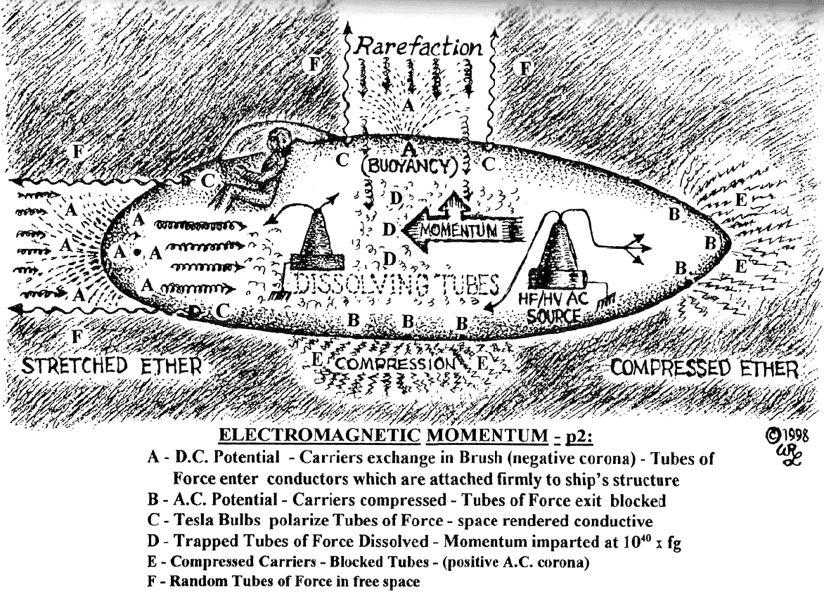
First, it is recommended that a flying model be built and tested before proceeding further, as it would be very disappointing to build an elaborate saucer which doesn’t work. The fundamental principle is simple: to electromagnetically synthesize momentum, employing a high voltage D.C. brush discharge, in the direction of desired acceleration, to draw in and cause the exchange of ether carriers, which also brings in the tubes of electrical force, and to cause the tubes to dissolve in the conductors of the ship, which imparts momentum to the conductors, at 90 degrees to the electric current and magnetic inductance.
In order to facilitate the dissolution of the tubes of force, an alternating current of sufficiently high frequency is utilized on the opposite end of the ship, to compress and block the ether carriers and tubes of force, so that they cannot pass out the rear, and are thereby forced to dissolve to impart momentum in the opposite direction. The hull should be accelerated, creating electromagnetic momentum in the desired direction almost instantaneously.
A Tesla coil is used to create a negative D.C. brush discharge on one electrode, and another Tesla coil is used on the opposite electrode, to create an A.C. high frequency, which compresses the ether carriers and tubes of force, and blocks their passage. These two electrodes comprise a “p2”—two different primaries—one—the D.C. brush— which draws in the tubes of force, and the other—the A.C. current—which blocks the ether carriers and forces the tubes of force to dissolve.
The D.C. brush produces “negative (“hairy”) corona”, and the high frequency A.C. produces “positive (“cloudy”) corona”. It is believed that this system not only creates instant momentum in the direction of the D.C. brush, but eliminates the problem of inertia in the direction of the A.C. high frequency current, so that the rate of acceleration is virtually unlimited, and the destructive effect of acceleration is eliminated, since all parts of the ship and its contents accelerate at the same rate, without inertia.
This also applies to instant turns, in which the force of acceleration acts on all parts of the ship and its contents, to re-orient the force of momentum on each atom and molecule, in the new direction, eliminating centrifugal force. The kind of ship shown by these plans however, is of what I call the “linear type”, which turns in a curving path, rather than in sharp angles, because this type of ship is easier to construct and control.
In order to properly control the currents from the Tesla coils, specially designed switches, relays, capacitors, dielectrics, inductors and conductors are required. In these hypothetical plans, I provide my own design, which could conceivably be built by a skilled home craftsman. I also describe what I believe to be a control system which will be practical, reliable, and easy to construct, probably similar to what Tesla used on his “Flivver” machine, his manned, electro-propulsive ship of the earliest type.
1. SIZE AND SHAPE
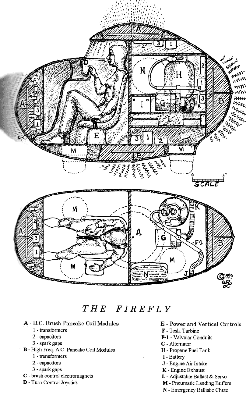
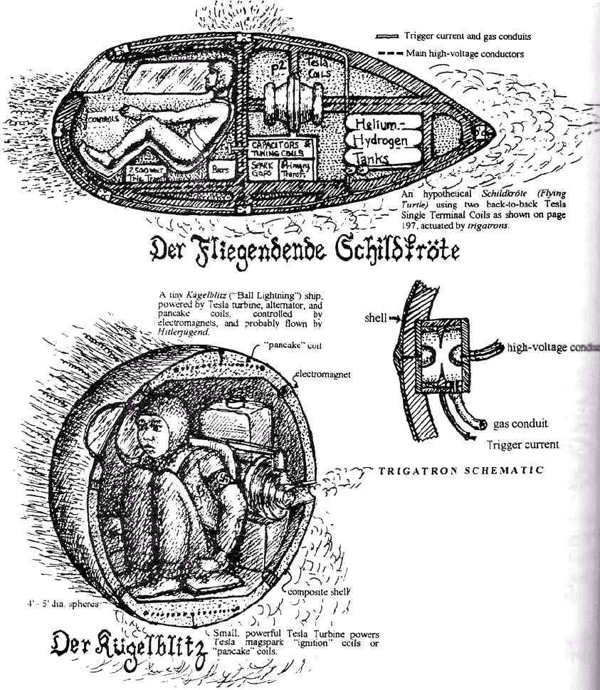
Since this ship is to be of the simplest type, it is no larger than required for one or two people. It is designed to be as small as possible, yet to have the necessary equipment and space for comfort. The general shape of the craft can be described as an oblate spheroid, the shape of a moving “point charge” system. The first manned ship built by Tesla was described as the approximate size and shape of a “gas stove”, which would be a sort of long, rectangular box on legs. The legs were presumably stand-off insulators so the craft could get off the ground.

I assume that it was of the linear type, with Tesla crouched inside, perhaps on some sort of support, which allowed his hands to be free for the controls, with his head pointed toward a small window at one end. Electromagnets on the “front”, with switching and polarity provisions to divert the brush to the right or left, would allow for complete control, with the ‘buoyancy’ control determining altitude.
The bottom and rear would be activated by the high frequency A.C. blocking current. If Tesla wanted to turn right, he would use the electromagnets to divert the brush so that the right corner was pulled, as the air pressure would cause the ship to swing around in a circular turn. To go down, all he had to do was to diminish the current to the top brush.
Since the most efficient application of electrical energy is desired, to conserve energy and to transmit the respective propulsive force effectively, with the least expenditure of energy, it is recommended to use rounded surfaces, similar to the design of electrostatic generators, the design of corona rings, or the design used by Tesla in his Wardenclyffe Tower electrodes—rather than sharp points, shapes, or edges—which tend to cause “point discharge”, the wasteful and uncoordinated leakage of electric charges into space in a manner which is unproductive.
Since the primary function is to get the ship off the ground and to remain stable while hovering, the upper surface area is generally a horizontal surface, but is spheroidally curved and somewhat symmetrical. I call the electrode from which a brush discharge is emitted at the center top of the ship, the “buoyancy electrode”. This electrode is used at almost all times during flight, in addition to an electrode which may be activated at the front of the ship, to cause horizontal acceleration and to turn the ship.
Apparently, the ship will not work without the high frequency A.C. blocking and compressing current to the rear and on the bottom, otherwise, anything with a D.C. brush discharge would take off and fly away at fantastic speed. There is always an “equal and opposite” reaction. In order for there to be a “reaction”, there must be a “disturbance to the equilibrium”. As the ether carriers continue to exchange, bringing in the tubes of force, there is nothing to prevent them from passing out the other end of the ship, so that there would be no “reaction”, and the ship would acquire no momentum.
As Tesla said, the A.C. current (at the rear and bottom of the ship), when of “sufficiently high frequency”, will draw ether carriers and tubes of force to itself, until they are so compressed that no further action will occur. This is apparently intended to “block” the field of gravity and to block inertia - like Dr. Cavour’s ‘door’, painted with “Cavourite - and to force the tubes of force in the ship’s forward conductors to dissolve, so that momentum is imparted to the conductors (and the ship to which they are attached), as J. J. Thomson said.
2. POWER SYSTEM
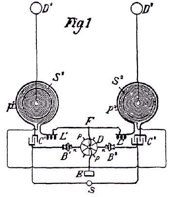
One of Tesla’s patents, Method for Signaling, Patent No. 723,188, which has the two primaries marked as “p1 “and “p2”—possibly the origin of the title “p2” given to the 1935-38 New Mexico project run by von Braun—shows an oscillator system having two separate pancake-coils, tuned differently, running off a common rotary spark gap and dynamo.
A copy of a drawing from that patent follows:

If one coil is tuned to one quarter wavelength, and the other to a full wavelength, they would comprise a D.C. brush circuit and a high frequency A.C. circuit, respectively. The A.C. circuit could be run at all times on the bottom and rear, with the brush being activated at the top to lift off, and to the front to go forward or turn.
I can’t recommend a better prime mover than the Tesla turbine, because of its compactness, light weight, and efficiency. Below are excerpts from Tesla’s Turbine patent #1,061,206 and related Valvular Conduit patent #1,329,559. Two conduits supply air and gas, respectively, to the firing chamber (second turbine):
The second edition of Free Energy Surprise, when issued, will include my complete set of plans, redesigned to be constructed using basic machine tools for the home builder.
The turbine shown will produce at least 30 break horsepower and operate at about 30,000 rpm., and should weigh no more than ten pounds, including the valvular conduits and firing chamber.
The firing chamber has a glow plug (the kind used in model airplane engines), and fires in a “reverberatory” way (the explosions come in rapid succession), producing a continuous supply of expanding hot gases, which enter the turbine on its outer edge as shown, and spiral between the disks toward the vents which are near the center shaft. I have routed the exhaust out one side of the turbine, through a single exhaust vent, rather than out both sides as Tesla did, to diminish turbulence, and to free one side of the turbine for the bearing mount and connection to the gearbox and mounting plate.
The exploding gases will not blow back through the valvular conduit, which was Tesla’s valve system having no moving parts, and will continue to move into the turbine inlet vent, as the combustion chamber continues to produce the pressurized gases.
Judging from the fact that the turbine will produce 30 hp on 125 lbs. steam, it should produce more horsepower on propane or gasoline, and should be adequate.
For the generator, I recommend a heavy duty high amperage automotive alternator, such as the type used on heavy equipment, or a high output, lightweight alternator designed for power generators, normally having an engine of about 30 hp.
It will be necessary to use step-down gearing to reduce the speed of the turbine, so that, at the optimum (most efficient) operating rpm of the turbine (about 25,000 rpm), it will be stepped down to the optimum operating rpm recommended for the alternator. For example, if the alternator is to run at 1,200 rpm., and the turbine at 25,000 rpm., the gearing would have to function at a 20:1 ratio. A battery will also be required to supply the appropriate exciter voltage, and to store electrical energy for appliances and other necessary on-demand current. Only herringbone gears should be used in the gearbox.
By using an unrectified A.C. current from the alternator, it should be possible to route it directly into the high voltage transformer, with a variac to regulate it. For example, if the alternator produces three cycles per revolution, at 1,200 rpm., it would produce the approximate 60 cycle current for the high voltage transformer. The high voltage transformer(s) should be capable of producing a high amperage output commensurate to the horsepower of the turbine.
A neon light transformer, producing .030 amps at 15 kv., would amount to only 450 watts in the secondary, for a generator which could produce 45 kw or more. To be on the safe side, you should use transformers for each pancake module which have high voltage ratings of at least 5 kw in their secondaries (totalling almost 50% of the alternator’s capacity). I can’t imagine that this system would be inadequate. This would be enough power to run about 50 Tesla coils of the powerful types which I have run off the neon light transformers.
3. HIGH VOLTAGE D.C. BRUSH DISCHARGE
The high voltage D.C. brush discharge allows equal exchange of the electric and magnetic tubes of force in opposite directions. The Tesla coil is tuned to one-quarter wavelength, emitting negative pulses which are so rapid that the current continues to flow in the secondary, during current reversals in the primary.
This steady D.C, “pseudo-electrostatic” brush discharge has a greater effect on the independent ether carriers, and ‘rarifies’ them, exerting an elastic, pulling force in the space in front of the ship. This induces the rapid exchange of the ether carriers through the front of the ship, and draws the tubes of force into the conductor. In the D.C., secondary conductor, the tubes of force have nowhere to go, and are forced to dissolve, as new tubes of force continue to be brought in. This imparts momentum to the conductor, which must be firmly attached to the ship.
The thing which makes the tuned Tesla coil the ideal contrivance for this purpose, is the fact tat the principles of high frequency inductance make it possible to create very high D.C. potentials, using a relatively small coil, which may be placed flat against the walls of the ship, powered by a compact alternator. This eliminates the need for the large and cumbersome parts of an electrostatic generator, which would produce only a fraction of the amperage of the Tesla coil, and a greatly diminished exchange of the ether carriers and influx of tubes of force. It has also been shown that a D.C. pulse produces a greater effect in Hall effect pumping than a steady D.C. current.25
The negative D.C. pulse discharges will leave the inside of a closed hollow conductive vessel—such as a saucer is—and appear on its outer surface, as Michael Faraday discovered, which conveniently protects the pilot, crew and internal contents of the saucer from the effects of electrostatic charges.
4. HIGH VOLTAGE,
HIGH FREQUENCY
A.C. CURRENT
The high frequency current, required to block the exchange of ether carriers and passage of the tubes of force through the rear of the ship, behaves with a “skin effect”, which means it travels over the surface atoms (the “skin”), rather than through the internal mass of the conductor, as well as the skin of other solid conductive bodies.
This phenomenon also provides some convenient protection for crew members from the effects of this type current. Aside from the phenomenon of the skin effect of high frequency alternating current, internal circuits must be highly insulated and shielded where necessary, with care given to shielding of the pilot (and crew or passenger) from possible high voltage radiation dangers.
The pancake-type coils have a higher threshold for arcing at a given voltage than cylindrical or conical ones, which makes them best for these very high voltage applications. Care must be taken at all times, in the design of high voltage circuits, that the close proximity of conductors having high opposite potentials is avoided, and sufficiently insulated and spaced where necessary. Silicone rubber, transformer oil, Formica, and plexiglass are good insulators, and there is a dielectric paste which is excellent.
There is a tendency for the air close to the conductors to become ionized, creating pathways for the current to leak and arc through space to other conductors of opposite potential, whenever within range, roughly governed by the parameters of 20 kv/cm., at sea level pressure, adjusted downward for higher altitude and correspondingly lower pressure, which requires that the space be increased for the same difference in potential. Internal high voltage corona leakage and arcing between conductors, components or contacts, can be suppressed by use of pressurized inert gas environments, increased air or gas pressures, solid, rubber, plastic, oil, or paste insulators of high dielectric strength.
25Beckman Instruments, Inc., Hall Effect Manual, Helipot Division, Fullerton, California.
5. VERTICAL ASCENT
5. VERTICAL ASCENT
AND DESCENT
Due to the tremendous superiority of the electrical attractive force over the gravitational and aerodynamic forces, it should be possible to fly a saucer with a greatly diminished electric power system, but the saucer’s control is a very sensitive matter, requiring the ability to activate the appropriate electrodes rapidly, in response to a need to change directions of movement, or to quickly correct inappropriate movements of the ship, because of its great speed and ability to “jump around” without inertial/momentive resistance.
The main buoyancy coil, mounted in an area above the cabin, provides the negative brush discharge, which, when paired with the high frequency A.C. coil, beneath the cabin floor, accelerates the ship upward, as the force is balanced to maintain the saucer at a particular vertical position. The high frequency current used on the bottom of the ship on hovering, seems to be the equivalent to Dr. Cavour’s “door”, which when shut, stops the gravitational effects from forcing the ship to accelerate toward the earth.
The description in 19th century physics literature, as I documented in Occult Ether Physics (especially the 2nd Edition), implies that a normal gravitating body moving relative to earth, within earth’s electric, magnetic and gravitational fields, naturally draws the tubes of force into itself, where they are dissolved to impart momentum.
The downward movement of the saucer can be effected by allowing it to drop by the force of gravity, with power diminished, though it can be effected more rapidly by a reversal of the forces which accelerate it upward, but, to eliminate unnecessary complexity and danger, I don’t recommend this for a prototype.
The discharge electrodes shown in these plans are of the “pancake-coil” type, which can be placed parallel to the interior walls of the ship, and will be the recipient of the momentum, which is imparted on the third axis, perpendicular to the flat side of the coil, at 90 degrees to the other two axes, which are the magnetic inductance and electric current axes. Placing the flat coils parallel to the outer walls will therefore orient the momentum perpendicular to the outer surface of the ship.
6. HORIZONTAL TRAVEL
force on each other due to their variations, but Tesla proved that the “ponderomotive force” is due to the respective rarefaction and compression of the ether carriers, produced by different kinds of currents (D.C, A.C, and rapidly varying electrostatic forces)26, and their effects
Horizontal travel is effected by a pairing, along the ship’s longitudinal axis, of the two electrodes, the D.C. brush at the front, and the high frequency A.C. current to the rear. It was believed at one time, by Heinrich Hertz25, that two systems of varying current should exert a ponderomotive force on the ether.
25 Ann. d Phys. xxxi [ 1887], p. 421; Hertz’s Electric Waves, translated by D.E. Jones, p. 29.
26 Nikola Tesla, Lecture Before the A.I.E.E., Columbia College, New York [May 20, 1891]; Nikola Tesla, Lecture Before the Institution of Electrical Engineers, London [Feb., 1892].
B. CONSTRUCTION
OF THE HULL
Due to the magnitude by which the electrical attractive force is greater than the gravitational attractive force, tremendous stress is created on the hull of a saucer, which must therefore be constructed very strongly. While a spherical shape readily lends itself to such requirements, internal structuring members and walls should be designed, constructed and positioned for maximum rigidity and strength, to prevent the possible pulling apart of, or crumpling of the hull, as this would be the supreme misfortune.
Construction of entrance and exit ports and other such contrivances, should anticipate powerful stresses, since openings are generally points of weakness. It is desirable that the hull have a smooth and continuous conductive outer surface, which has little or no small diameter protuberances, and as few weak or “blank” spots in it as possible, caused by such things as windows (See “C. Simplified Drawings and Plans” below for available excellent source of technical construction literature with materials suppliers). Windows must be of strong, thick material, firmly attached.
Continues…
For far more see
FROM http://www.ufohowto.com/index.htm
Xtra image - https://d3qcduphvv2yxi.cloudfront.net/assets/1988841/lightbox/eb030a022aca7ce7528e57c3aad394b5.jpg?1283505249
For further enlightening information enter a word or phrase into the search box @ New Illuminati or click on any label/tag at the bottom of the page @ http://nexusilluminati.blogspot.com
And see
The Her(m)etic Hermit - http://hermetic.blog.com
New Illuminati – http://nexusilluminati.blogspot.com
New Illuminati on Facebook - http://www.facebook.com/pages/New-Illuminati/320674219559
This material is published under Creative Commons Copyright (unless an individual item is declared otherwise by copyright holder) – reproduction for non-profit use is permitted & encouraged, if you give attribution to the work & author - and please include a (preferably active) link to the original along with this notice. Feel free to make non-commercial hard (printed) or software copies or mirror sites - you never know how long something will stay glued to the web – but remember attribution! If you like what you see, please send a tiny donation or leave a comment – and thanks for reading this far…
From the New Illuminati – http://nexusilluminati.blogspot.com


hello, i will be constructing a anti-gravity craft soon. do you think this tesla craft is more efficient than electrogravitics?
ReplyDeleteTesla's craft ARE electrogravitic - and can be built with technology that's more than a century old.
ReplyDeleteSee Nikola Tesla's Flying Saucer @ http://nexusilluminati.blogspot.com/2010/11/nikola-teslas-flying-saucer.html
ReplyDeleteHello it mentioned that a neon transformer would be inadequate, i dont suppose there is any right type for sale so one must be built and i found this info about a tesla transformer would this be the right type to make? :
ReplyDeleteThe electricity goes into a Tesla transformer; again, one
transformer for each capacitor. In an oil tank to insulate the
windings and for cooling, and supported internally by wood, or
plastic, pipe and fittings, each Tesla transformer looks like a
short wider pipe that is moved along a longer, narrower pipe by an
insulated non-electric cable handle. The short pipe, the primary,
is 6 to 10 windings (loops) of wire co nected in series to the long
pipe. The secondary is 460 to 600 windings, at the low voltage and
frequency end.
tHE aLEN USES A CENTRALIZED ULTRA CAPACITO OF VERY HIGH VOLTAGES FOR THE eLECTRODES TO FUNCTION
ReplyDeleteThe Alien Sauser has a Centralized Capactor of a very high Voltage out put ?for the Electrodes to Function,and a nuclear reactor is the scource ?to turn the generators for the Electricity out put,via an inverter for the 50,000 or more Volts,and the speed of this Flying Sauser is?18,000 miles per hour,with unlimited range,and the uranium pellets are intercgangeable?every three years!!! Recently Roy Subrahta a NASA Engineer ,Invented somthing,similar to the Alien Craft,,using Plasma,in which it charged the air into Plasma positive ,for power,ionizing the very air via electrodes buried under the skins of the Sauser Craft,and controlled by the pilot of the Flying Sauser through a Reostahts,that in turn?controls the Left and right turn of the said ,Flying Sauser,but this system of propulsion,is for atmospheric environment only,thats why,they cant fly to outer space ?becuz there is no air,so?they use their Mother ships for space travel,and using a system of Space-Warp propulsion,for outer space travel,or pgoton-Drive!!! AMEN
interesting nice to know someone finnally gives out this information
ReplyDeleteThere I can see the flying prototype?
ReplyDeletemay i suggest just buying all of william lyne's books off of amazon, which is were this information was copied from
ReplyDelete