HOW TO BUILD
An ELECTROGRAVITIC
FLYING SAUCER 2

Luke Fortune, who is not a debunker, has released over 3500 pages of proof that man has had the ability to build UFO craft, in replicable form over the last 100 years.
Part 2 - See Part 1
POWER PLANT

Since the electrical attractive force is so much greater than the gravitational attractive force, it is logical that a relatively small engine, such as the Tesla turbine, or a snowmobile or motorcycle engine, would be adequate to power an alternator of sufficient power for this size saucer. Tesla designed his tiny turbines and remarkable high frequency alternators for this purpose, and they would be preferable.
An independent air intake and exhaust system, separate from the air supply for the cabin, must be provided, with careful attention to preclude the mixture of exhaust gases with the air supply for crew and pilot. Batteries may be sufficient to supply electrical power for a saucer, with a small engine used periodically to recharge the battery system, as needed. As shown below in “Special Supplementary Notation on the WW II German Flying Saucers”, construction of manned, ‘hot-rod’-type saucers or spheres, perhaps only four feet in diameter, may be feasible, possibly using automotive spark coils (perhaps similar to some of the “foo fighters” seen and photographed by allied bomber gunnery crews, in the skies of WW II Germany).
The atmospheric nitrogen-oxygen combustion system invented by Tesla, for the production of electrical energy from the air, is too complex to be covered here, and there is insufficient information as to just exactly how the system was constructed and used to produce useful energy.
2. SEATING AND VISIBILITY
Ultra-light, strong, fiberglass bucket seats with seat belts, are recommended. The closer the pilot’s eyes to the windshield, the smaller the windows required for visibility, with care taken to electrically insulate the pilot’s head from the ceiling. A spherical shape will provide better visibility than a ‘discus’ shape, and a wide-angle optical viewer might be provided directly downward, between a solo pilot’s legs, if desired.
This type of saucer involves a restricted pilot position, but since the saucer is so fast, satisfying flights, over great distances, should be of short duration. Small video cameras such as those often used on race cars or by skiers, having wide angle lenses, might be mounted in the saucer surface, with view screens around the interior of the cabin.
For a small, ‘hot-rod’ saucer as these plans describe, there are several inconveniences which must be tolerated in the name of practicality and economy. The more wealthy builder will naturally find a way to include as much luxury and high-tech controls, accessories and other facilities as he can afford or desire.
3. FLIGHT SUIT

The flight suit should provide electrical and heat insulation, with ultraviolet protection for the eyes. An insulated, cold-water wet suit might work well. Since a pilot will be looking out ports which are near the hull surface, the helmet should provide extra thick electrical insulation, to prevent arcing or electric shock to the head. In general, the suit should provide U.V. radiation protection, preferably by use of a special plastic already developed for this purpose. (NOTE: It was rumored early in the program, in the ‘50s, that only women pilots were used, since the male scrotal cavity is particularly sensitive to the electrical radiation problems of the saucers.)
Ironically, the kind of pull-over headgear, used by actors or pilots, often used to fake the appearances of “aliens”, might be an ideal design for a saucer pilot’s headgear, with thick layers of foam insulation in the top (representing the bulbous brain cavities often depicted on the phony aliens), and the sunglass-lens eyes covers would provide U.V. protection.
SIMPLIFIED DRAWINGS & PLANS

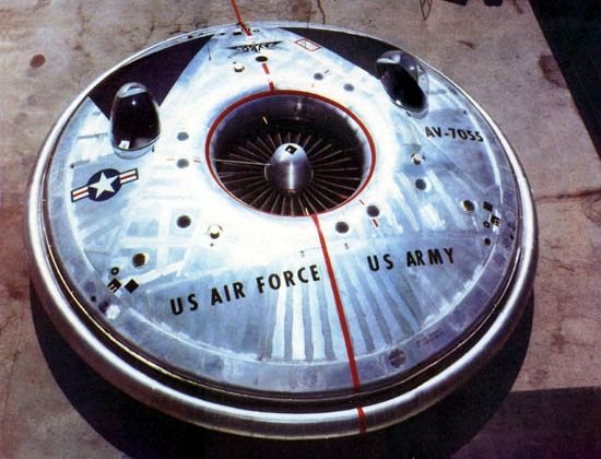
The following drawings, including nomenclature, [except for imported UFO images in colour - Ed] are presented in a simplified format. The details of each particular part or section, are left to the creative imagination, ingenuity and resourcefulness of the individual reader or experimenter, with the author presenting his own suggested design, predicated to provide the least possible obstacles in procurement of materials and actual construction.
The skilled experimenter will also recognize that there are relatively simple methods for construction of a scientifically adequate, test scale model, and only a fool would embark on such a project without making such a test, with care taken to insure that the model is suspended by insulative string running through pullies, so that the power may not drain to ground. Such details of saucer construction as particular metals and other materials, fabrication and technology, are generally omitted from these plans, since a complete, detailed set of working drawings, with accompanying technical literature, could conceivably require ten times the length of this book.
As an excellent source for materials and techniques, I recommend Andrew C. Marshall’s Composite Basics28. This book even describes honeycomb metals and other metal/plastic bonding and structural materials and techniques, etc., and provides sources for a wealth of expert home-built aircraft construction materials and literature of many kinds. Aluminum, though light, may not be the best metal, because there are so many bonding problems with the metal. I am recommending stainless steel, since the electromagnetic flux used to divert the brush discharge for turning must be able to pass through the outer shell.
28Andrew C. Marshall, Composite Basics [1994, Marshall Consulting, 720 Appaloosa Dr., Walnut Creek, Ca. 94596]

1. Special Supplementary Notations on The WWII German Flying Saucers: In this short summary, I will avoid suspected misinformation, or material which is unrealistically speculative.
There were purportedly several inventors working in Nazi Germany on various types of flying saucers, not all of which were electro-propulsive in concept, meant to operate on rocket, jet, turbojet, or prop-driven reactions of the aerodynamic type. All the video or literary material available to me, concerned this “aerodynamic” type, were either misinformational, or grossly ill-conceived “science” of the La La Land variety, seeming to be mostly contemporary Austrian new age ‘thinking’ or CIA-concocted garbage, containing only grains of truth.
For example, there seems to be valid documentation concerning one example, the Habermohl “Pflugerad” (“Flying Wheel”) - which was little more than a re-designed gyrocopter—which actually may have gotten off the ground, though even in the supposed ‘documents’, was said to be unstable and dangerous to fly. It combined a gyrocopter or helicopter rotor in a wheel shape, concentrically rotating around a ball-shaped cockpit. It experienced several crashes during tests, probably because the rotor gave it too much gyrostability, so that it was unmaneuverable, there being no way to decouple the rotor/gyro from the airframe, during turns or changes in attitude.
Some models showed a vertical stabilizer and rudder on the rear of the central non-rotating cockpit section, to turn it in the direction of flight. A rather good idea later used on “jet copters”, was rocket or jet engines attached to the rotor, which eliminated the torque problem normally encountered with shaft-driven rotors.
The inertial guidance system (“Peiltochterkompass”, or “polar slave compass”) was built to meet the requirements of the “full electric” “Kreisel Teller” , because the electrostatic “Faraday cage” effect created by its propulsion system made a normal compass worthless, and the high speeds (c. 9,000 m.p.h.), zig-zag maneuverability, precession, and poor visibility created navigational problems which required a special, non-magnetic compass.

The Peiltochterkompass was coupled to a “Meisterkreiselkompass” (“master gyrocompass”) mounted on gimbals, which generated its own angular momentum, and operated independent to the earth’s gravity and the ship’s momentum or inertia. This would be true even if the saucer externally cancelled the effects of gravity, inertia and momentum since, just as the sun transfers momentum to the earth by electrical current, the saucer power system transfers angular momentum to the gyro.
Moving freely on its gimbals, the master gyrocompass pointed in the same direction all the time, no matter which way the ship turned, held into position by its angular momentum, as the motor on the slave compass was actuated when needed to turn the compass indicator dial in the direction of travel.
This book is the only known documentation concerning the “KT-p2” project, which from my analysis appeared to be the only true electro-propulsive saucer, and hence true “UFO” possessed by the Germans. In reiteration, any other kind of “saucer” is not a “saucer” at all, but only some sort of jet, rocket, or fan-driven plane, which by coincidence was only shaped like a saucer. There is nothing inherent in the “saucer” shape which makes it particularly advantageous over a conventional aircraft, and in most cases, is a disadvantage, except in the context of electro-propulsion only, and this only if it is desired to have instant 360-degree maneuverability.
The “saucer” projects carried out in Czechoslovakia were clearly disinformational, given the fact that von Braun had the electro-propulsive type as early as 1936 by my documentation. This has come as an embarrassment to those who have put so much stock in the so-called “S.S. documents from Wiener Neustadt”, which came under the jurisdiction of the CIA and were therefore misinformational. It would be wise of you to observe who among the “UFOlogy” network has been first to make so much of these documents, as well as who among them have been suckered in by them.
It is likely that true saucers were available at the Wiener Neustadt base of General Otto Skorzeny, but were not as described in the tampered literature. It appears that the O.S.I. prepared the disinformation, and disseminated it with the help of Skorzeny, who was one of the first to make such deals to stay out of jail. Skorzeny was also crafty enough to conceal several stashes of high tech documentation and plans, so that he could coerce either the Soviets or the Allies into giving him the protection he desired.

The O.S.I. directed attention to the misinformation, through UFOlogy channels, just in time to anticipate my book. Many suckers fail to realize that all German saucer materials had already fallen under the jurisdiction of the CIA O.S.S.), even before the armistice.
One writer/speaker has attempted to distinguish between “saucers of the secret societies”, and “saucers which were secret weapons of the Third Reich”. What is secret” is secret, and the fact that the electro-propulsive saucers were used by the Third Reich in its air defenses meant that the “secret societies” scenario is only a fantasy encouraged by the CIA, while the Gestapo clearly could qualify as a “secret society”. How secret can it get?
My material is obviously more secret than the Wiener Neustadt stuff, and I had no help from the “Knights Templars” or anyone else, and have had to fight tooth and nail all the way to the day my first edition was finally published, and am still struggling. Most of my analysis of the saucer’s propulsion system was extrapolated from my 1953 sighting, confirmed by what I have learned from my Peiltochterkompass. In the years since the publishing of my first edition, read by many engineers and scientists, some of whom are experts on German aircraft of all kinds, no one has produced any mention of a “Peiltochterkompass” or the “KT-p2 Projekt”, from another German source or any other. This alone proves the German “documentation” has been tampered with, because of the conspicuous omission of this important project.
From these facts, it is my assessment that the so-called “S.S. documents” are either complete fakes, or have been seriously tampered with for misinformational purposes. For example, one type of German ship is referred to in the documents by the name “Kraut Meteor”. Despite the fact that this was sometimes how the Allies referred to it on occasion, the Germans wouldn’t have called it that in their own documents, which would be tantamount to Idi Amin Dada building an aircraft, and calling it the “Nigger Watermelon”.

I very seriously doubt that Hitler would have permitted the use of such derogatory and “decadent” American slang to name a supposed ‘super aircraft’ of the Third Reich. Having already been suckered in once by some of this material, I won’t do it again, and I urge extreme caution in accepting and repeating this material, unless you want to be made a sucker out of.
Recently, I was contacted by a Californian person who sent me a copy of W.A. Harbison’s book, Inception (Dell, 1991). He was under the impression that Harbison’s book had pre-empted mine. Not so. Harbison’s book not only was fiction (and very interesting at that), but was based on the misconception that “German” flying saucers were the first ones, that they used an aerodynamic “boundary layer” air propulsion system purportedly invented by a fictitious American named John Wilson, and that the saucers we see today are headquartered out of an elaborate underground city built under the ice of Antarctica, run by the S.S. and worked by slave labor. Boundary-layer “saucers” would not be true “flying saucers”, but would only be unusual “air-planes” shaped like flying saucers.
As proven by my Peiltochterkompass and my sightings and documentation, the German saucers were electro-propulsive Tesla craft (requiring an inertial navigation system, because of the high-voltage electrostatic discharges and “Faraday cage” effects), some of which had 360-degree peripheral maneuverability in 30-degree increments, just as I observed between 1947-53, in the night skies of West Texas.
The purported Schauberger ships (the only information we really have are photos of models built by Felix Schauberger), purportedly built in Czechoslovakia, were supposedly designed to use an “implosion turbine” to generate the power to drive an ‘air-blower’ intended to propel the ship. As such, it was little more than a (flying?) air conditioning vent, with an unusual engine, and couldn’t have gotten off the ground.
And even if by some miracle it could have gotten off the ground, it couldn’t have gone over 300 m.p.h., with the dumpy design, much less over 1,000 m.p.h. as claimed by misinformationists, especially since there is not even reliable information that the ship was ever built. It is too easy to say “the Russians got it”, and even if it had been built and had flown, it wouldn’t be worth classifying, any more than the little engine-powered UFO toys, which at least were more feasible, and are known to actually fly.
There was purportedly a ship designed by Miethe said to be powered by 12 BMW engines—claimed in documents to run on helium—but said to use the “boundary layer” aerodynamics of Prandtl. Such a system, if true, automatically ruled out electro-propulsive ships. It is my belief that if any of the photos are partially real, the purported name and propulsion system were misrepresented, to throw investigators off the possibility of electro-propulsive ships. There is a photo (real or fake?) purporting to show Miethe explaining this type to Hitler on Apr. 7, 1944. It was purportedly tested in November, 1943, which would be only one month after the manufacture date of my Peiltochterkompass, which raises a probability against mere coincidence.
For that reason, I believe that some of the photos—but not the usual ‘technical descriptions’—of these ships, may be genuine. The drawings of the basic internal structures may also be somewhat accurate, disregarding the misinterpretations given to them. Large, round ball shapes are shown in the drawings, and three of these are shown in the large “mother ships” (what I call “flying submarines”). These ball shapes could have been liquid helium fuel tanks. A “helium power” system could run “BMW engines”, as shown by the Papp engine shown in the Appendices.
Twelve engines would suggest that each engine drove a separate electrical generator around the periphery of the saucer, which is consistent with the Peiltochterkompass design. The “Miethe saucer” could be from the “KT-p2 Projekt”, the particulars (name, power system, etc.) having been obliterated and faked with misinformation. Though labels and nomenclatures of drawings allegedly from Wiener Neustadt appear to have been altered—especially the written documents alleged to have been with them, which contain silly language—some of the physical designs makes sense in terms of electro-propulsive ships, when “corrected” by my material.
One sketch shows a manned “Flying Turtle”, which is very similar to the ones I saw in the WW II 8th A.F. film taken by a B-17 bomber crew. I saw this film while a member of the 26th Strategic Reconnaissance Wing, Operations Intelligence Division, Strategic Air Command, Lockbourne, A.F.B., Ohio, in late 1957. We viewed the film with other intelligence personnel, several of whom had participated in the actual bombing raids in which the film was shot. My O.I.C., Lt. Col. Edward R. Jirles, was involved with Operation Paperclip, as he was among the first Army C.I.C. personnel in the Rheinland. In fact, he was responsible for hunting down and bringing in the “Werewolves”—the last fanatical holdouts of the S.S.—for S.E.A.T.O.
Capt. Weismann still carried 9 pieces of shrapnel in his body which he received as one of the heroes who bombed the Ploesti oil fields in Romania, and was sufficiently recuperated in time to be aboard a bomber for the “foo fighter” incidents. Contrary to misinformation, the “foo fighters” were not radio-controlled, unmanned craft, but were small electro-propulsive ships flown by pilots, probably Hitlerjugend.
German daredevils apparently flew these things around the bombers to disrupt their electrical equipment and ignition systems, and to draw their fire. Disruption of the equipment would have required no special equipment, since their dynamic electromagnetic fields and high frequency corona would have rendered the desired effect on allied aircraft, just as one shut down the electrical system on my father’s car in 1957, just outside Levelland, Texas. That ship was about 200 feet long and was egg shaped, similar to the Flying Turtles and to those seen by Lonnie Zamora near Soccorro, New Mexico.


Since the “Flying Turtle” was perhaps the simplest of all the German types, I present a simplified set of hypothetical drawings and plans for it. We have no complete, detailed photos or drawings of its design, other than the 8th A.F. films I saw in 1957, and a preliminary sketch from German sources, which I give partial credence to, and present for you with as good an interpretation as possible. The advantage of the Flying Turtle was its good visibility, and its cheap, compact, one-man, simple “hot rod” design, audaciously sacrificing everything to function, to tear into the skies and interfere with the horrible Allied “fire-bombings” that killed several hundred thousand civilians in the Hamburg and Dresden areas.
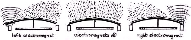
Because of its oblong (“turtle-shell-shaped”) design, the control system on these craft appeared to be simplified, with electromagnets in front to turn the ship. The blast of the air was relied on to pull the ship into line as the force was applied, to get the desired maneuverability in the simplest and most direct way. This explains perfectly how the “Foo Fighters” were able to fly in a spiraling pathway.
The truth of the air combat over Germany reveals heroic tales of young daredevils and wily old veterans, such as Adolf Galland, who not only flew with only one leg and one eye, but parachuted out of several shot-up Gustavs to return immediately to the sky to fight again, over and over, until there were no more planes to fly 29. Many of Germany’s pilots fought hard, well, valorously, and honorably to the bitter end.
In the film I saw, in which the Flying Turtles circled the B-17s helically, along their flight paths, the gunners were unable to shoot them because they moved so fast, although they appeared to hit some of the much slower Me-163 “Komets” (c. 500 m.p.h.) which accompanied the Flying Turtles. The Komets were cheaply built “disposable ships”, abandoned in the sky once their rocket fuel was expended. In one shot, a Komet pilot could be seen bailing out.


29Heinz Knocke, I Flew For the Fuehrer.
By comparison of both size and speed between the Komet and a Flying Turtle (moving more than twice as fast as the Komet), it was obvious that the central body of the Turtle was larger than the Komet’s, and was going at least 1,000 m.p.h., in a helical path. This maneuver would be the result of the pilots simultaneous actuation of both the “up” and “right” modes, in typical “joystick” fashion. These ships must have required a lot of dexterity, like a video game or a skate board. The speed was no surprise to me, since the saucer I saw in 1953 (about 5 years before I saw the film) was going at least that fast when it did its 90-degree turns.
Since my discovery of how Tesla controlled the brush discharge, to turn the craft, my plans show only one front electrode, with the “buoyancy” coils used to create the “up” and “down” movement. (Actually, an electro-propulsive ship could be flown with only one set of coils, by diverting the brush at the top to ‘swing’ the ship sideways “pendulum” fashion, but the speed would not be nearly so high.) Since the momentum is imparted to the conductor at 90 degrees to the electric current and magnetic inductance, the flat, pancake types, which can be firmly imbedded inside the ship’s shell, are ideal. One would be placed inside the hemispherical nose. A type of simple joy-stick— controlling the electromagnets to the two sides of the front coil—divert the brush discharge in the desired direction, as the body of the craft is swung around by the air to the corresponding curving pathway, turning the craft right, left, or straight ahead.
Intelligence agencies have exerted tremendous effort to obliterate the facts regarding combat reports of German flying saucers, even inducing false reports of post- war German and Austrian “new-age” type researchers, by feeding them misinformation. Some of the researchers even relied on information obtained from the FBI by FOIA procedures. They just can’t get it through their heads, that NO CURRENTLY CLASSIFIED INFORMATION CAN BE OBTAINED BY A CITIZEN THROUGH THE FOIA.
All such information has been “screened out”. Released documents which (once) contained classified references have the classified portions censored. That’s what all those blacked out areas are, stupids! In addition, under the National Security Act, completely fabricated information is often released through the FBI, under the FOIA, to mislead researchers who seek to discover classified secrets. What better way to sucker in those who think that certain “documents” released by the FBI are necessarily valid?
So-called ‘technical’ descriptions, according to dupes or those who pretend to know, are downright stupid. For example, the “Feuerball” (“Fireball”) is described as being a ‘circular’ or ‘spherical’, remote-controlled craft, from one to two meters in diameter, powered by a flat (radial) turbo-jet engine, which rotated the outer periphery around its axis, creating its “glowing” appearance from the effects of the expulsion of “over-rich” jet exhaust, as it spun around.30 Even more ridiculous, it contained a Klystron tube (developed around 1939 by the Varian brothers, for Sperry Gyroscope Company, in America), which pulsed synchronously with Allied radar, making it invisible to radar. 31 If stealth technology were so simple everyone would have it.
These descriptions just don’t cut the mustard. There was no way to make a remote- controlled device which did all the things reported, and the conspicuous effort was to avoid the categories, “electro-propulsive” and “manned flying saucers”.
30Haarmann, D. H. (1983), Geheime Wundervaffen (supra); Ratthofer, Norbert Juergen (no date), Demnaechst “Endkampf um die Erde”, Vienna, Austria; Flugscheiben und Andere Deutsche und Japanische Geheim und Wunderwaffen im Zweiten Weltkrieg, Sierndorf, Austria.
31Haarmann, Ratthofer (supra).
2. THE TWO BASIC TYPES OF GERMAN SAUCERS:

1. The ovoidal type, (or “linear type”) which flew lengthwise, and included the “Flying Turtles”, “Mother Ships”, and “egg-shapes” (which in some cases appeared to have more cylindrical shapes, like the “cigar” types, probably due to the necessity to use the most convenient means of fabrication and control at the time).
2. the silvery disk type, which flew peripherally, such as the ones seen by my mother, with some alterations to produce the “double-wok” shape seen by us in 1953.
There are some very close correlations between the alleged “Vril” ships and those seen by my mother and the entire personnel of the City Hall in Kermit, in 1950, and the ones seen by our entire family in 1953.1 have some friends who saw a ship similar to the Vril type (with a slot around its center), near Pecos, New Mexico a few years back. If the so-called Miethe ship was electro-propulsive, the “12 BMW engines” idea was probably misinformational.
A “boundary-layer/flying air conditioning vent”-type ship couldn’t have lifted off with the 3” tank cannon and turret alleged, even with 12 BMW engines. The measly vents would have carried insufficient thrust, and the air friction would have literally burned up the ship. Consistent with my mother’s information from Roswell and Alamogordo friends in 1948, helium was probably used as fuel in the German KT-p2 ships, which is the probable reason the Zeppelin program was abandoned, since all the helium was needed for flying saucer fuel. Besides, why have Zeppelins when you can have flying saucers, using similar construction techniques?
The helium reactors and the KT-p2 ships probably worked as follows:
NOTE: It is probable that a large Tesla coil system (2 coils for each direction, one for AC. and the other for D.C.) surrounded the cockpit area, triggered in 12 peripheral directions by “trigatrons”—triggered, helium-filled spark gaps—fired by 2,500-volt D.C. trigger currents, actuated by relays connected to the Peiltochterkompass. These could have controlled the discharges on demand, on the hull, thus easing problem of handling such high voltage currents. German technology on trigatrons was first made available to American electrical engineers at large, in 194632. Very little of this information was declassified even by 1959.
The following illustrations regard my view of various German WWII ships:
32Published Proceedings of Institute of Electrical Engineering [Proc. IEE, Vol. 93,1959].
3. Recent Notes Regarding American UFOs
In 1995, just after I had completed the manuscript for my second edition in August, an “Aurora” crashed and burned near La Luz, New Mexico, just to the north of Alamogordo and Holloman Air Force Base. This material developed too late for me to include in the second edition.
Around five days after the crash, while at the intersection of Old Pecos Trail and Rodeo Road at the southeast corner of Santa Fe, I saw a gray, ‘pug-nosed’ stake bed truck which had exited 1-25 from the south, as it stopped at a light. It had a CIA license plate on the center front of its bumper. As it turned left to go west on Rodeo Road— which goes across the south side of Santa Fe—I noticed that it had a tarpaulin on its bed covering some debris. It went west to Cerrillos Road, turned north to Siler Road, then made a left down Siler, and took a right down a street leading to a recycling center which I often went to. There, it unloaded its ‘salvage’.
The following day, I examined the debris, and even disassembled a component. The salvage included the following (drawn to the best of my recollection):
The debris was blackened from the burning, and someone had taken a sledge hammer to the dish, in attempt to deface it, but failed to break a single “power-vac”. The entire assembly appeared to be a high-amperage switching system which carried 15.5 Kv current to two places at a time, totaling twelve in all, in bipolar pairs. This seemed to confirm the rumor that the “Aurora” could hover and use “UFO-like” electro-propulsive technology, in addition to its normal turbojet power.
It is interesting that the name “Aurora” is used for this craft, since the discoveries by Kristian Birkeland and Hannes Alfven, that the Aurora Borealis is a giant current from the sun into Earth’s north pole, which transfers angular momentum from the sun to the earth, and showed the relation to Tesla’s electro-propulsive technology and Dynamic Theory of Gravity. The principle was illustrated by the sighting made by myself and several others as I sat in a hot tub at the Ten Thousand Waves Japanese Bath House near Santa Fe, on the evening of Jan. 26, 1996 (illustrated on page 181). The brush discharge extended above and ahead of the ship as momentum was transferred to it from the ether carriers.
The usual practice in handling debris from a crashed classified aircraft, such as the Aurora mentioned above, is to separate it and haul it to the four winds, using several salvage yards, to avoid detection or identification of the debris, but how could I have missed it with the CIA stakebed, only days after the Aurora crash, coming from the south, with a tarpaulin-covered pile of debris on its bed? Why didn’t they just fire off flares to signal their arrival?
Word apparently reached the CIA that I had examined the debris, since the salvage yard owner created some phony reasons to ban me from his yard. He said he had to play ball with the spooks, or they won’t bring him any more salvage. The time will eventually come when debris from salvaged saucers will become as common as that from old cars, and there will even be “used saucer lots”.

The oblong, lozenge-shaped ship with rounded edges, was about 10,000 feet away, and executed a perfect, circular flight in around ten seconds. Since its circle was around 30 degrees across, its speed was around 2,000 mph. It was around ¾” long at arm’s length, which means that it was around 400 feet long, about 250 feet wide, and appeared to be about 50 feet thick. In other words, the ship was about the size of a five-story building which occupied the shape of the area inside the track around a football field.
On July 19, 1998, 9:21 P.M., my son and I sighted a couple of huge, saucer-shaped ships, as we exited Furr ‘s Food Emporium, a large grocery store on St. Michael’s Drive, on the southeast side of Santa Fe. The ships were hovering and maneuvering between Santa Fe and the ‘tech’ areas to the south of Los Alamos National Laboratory. Due to the apparent distance to these ships—at least five miles—and their relative size, they were very large, several hundred feet across.
One ship hovered horizontally for a short time, while the other appeared to be hovering at an angle, showing its bottom, which had four large, red lights on it. The horizontal ship had a single row of red lights around its middle, in what appeared to be a trough.
These round red lights, which had to be around five to ten feet in diameter, ‘throbbed’ in sequence, from left to right, becoming bright then dim, one after the other. These were apparently to stabilize the ship’s precession, and the fact that they ‘throbbed’—increased and diminished gradually in power, rather than “flashed” abruptly—indicated that they smoothed out the transition of force from one electrode to another. This would produce a more stable effect to counteract the precession problem.
The large lights each had a hexagonal, ‘honeycomb-like’ pattern, indicating that they were composed of many smaller infra-red lights, each mounted in hexagonal frames. This was probably because of the difficulty in getting larger I.R. lights, and the fact that, even though one light might burn out, the others would remain to function until the burnt out lights could be replaced. The I.R. emissions seem to have the opposite effect on the brush as a magnetic field, inducing the brush to follow the beam to counteract its tendency to spin, since the spinning creates the precession when the ship is hovering. The I.R. lights are to stabilize the ships. Here is a simplified drawing:
4. MY FLYING SAUCER DRAWINGS AND PLANS:
Preliminary Technical Background
Having determined that a DC. brush discharge induces movement in the direction it is pointed, by “rarifying” and stretching the ether, Tesla did intensive research with the phenomenon of rotating brush discharge, and how it can be controlled.33 This research led up to Tesla’s proof of concept, by 1894. The rotation of the brush, caused by rotation of a magnetic field, is the apparent cause of precession of spinning bodies, and of non-spinning flying saucers. Since the brush induces movement in the direction pointed, its rotation causes the precessive oscillations. This is also consistent with the rotation of the brush clockwise in the northern hemisphere, and counterclockwise in the southern hemisphere. Since a spinning body carries electrostatic charges as it spins, it generates an invisible brush which moves at a slower rpm, to create precessive movement. Here, Tesla artificially created a rotating brush by inductance, in a non-spinning body.
P2 (or p2) is apparently two primaries, since two identical pancake secondaries can respond at different wave forms, determined by tuning in each of the two primaries. At one-quarter wave, the secondary will create a D.C. brush discharge. Referring to the illustration on page 197, Tesla’s patent #723,188, Method of Signalling, P1 and P2 are the two differently tuned pancake coil primaries, each having identical secondaries, run on the same system, which makes them appropriate for electropulsion.
An electrostatic generator is unwieldy and has a low output for its size. The problem Tesla faced was how to produce a pseudo-electrostatic D.C. brush with his small, light-weight high frequency coils. In reiteration, in the page 197 illustration, the coil to the left can be tuned to a quarter wavelength, to produce the brush discharge, while the coil to the right is tuned to a half or full wave, constituting a high frequency alternating current. The brush enables the ether carriers and tubes of force to enter the ship’s conductors (the metallic shell), while the other coil compresses the ether carriers so that no tubes of force can pass, so that the ship will have no inertial resistance to hold it back, and it can be accelerated quickly as well as turned on a dime.
Since the direction of momentum will be normal to the surface of the conductor, the brush can be diverted around a curved surface which is perpendicular to the direction of desired movement. It was necessary for Tesla to learn how to control the position of the brush, since a brush-control system (magnets) would make it unnecessary to have a cumbersome system of different coils for every direction. With a simple two electrode system, the ship could be propelled in any desired direction. As stated by Tesla 34,
“The rotation may be reversed by a magnet kept at some distance.” “...the fact that the brush turns, as far as I could observe, in any position, would speak for this view.” In his vacuum tube experiments with the brush, using concentric (double, inner and outer) bulbs, with a central emission electrode, Tesla stated: “As to the cause of the formation of the brush or stream, I think it is due to the electrostatic action of the globe and the dissymmetry of the parts... “, saying that if the two bulbs had been perfect, concentric spheres, with identical quality and thickness of glass, he thought the brush would not form, since “...the tendency to pass would be equal on all sides.”
33Nikola Tesla, Experiments with Alternate Currents of High Potential and High Frequency (Lecture before the Institute of Electrical Engineers, London, 1892) McGraw Publishing Co., New York (1904).
34Nikola Tesla, Experiments, etc. (Supra) p. 48.
In 1899, after the London lecture, Tesla stated that he had developed what he called his “single terminal coil”35. The new coil, which could be in a cone shape or of the “pancake” type, could be tuned to one-quarter wave to produce the brush discharge by means of impulses which have a negative preponderance, or tuned to the half or full wave, to produce the high frequency A.C. current. As said by Tesla earlier 36, “...in alternating currents of very high frequency the positive and negative impulses are not equal, but that one always preponderates over the other.” The D.C. nature of high frequency quarter-wave pulses have been similarly analyzed in modern times37, as follows (in pertinent part, emphasis mine): “Since electromagnetic effects are not transmitted instantly from point to point in space...there is a time lag between changes in charge and current distribution on the dipole” which “...allows some of the energy to continue flowing outward even though conditions at the dipole may have changed to indicate an inward flow of energy...as ij some of the electric and magnetic field has become detached from the dipole or ‘shaken off’ by the oscillation. “ The intensity of the emitted wave is dependent upon the increased frequency, and the time lag becomes more significant, since “...the power radiated varies as the fourth power of the frequency.”
Tesla moved his primary to the outside of his new “single terminal coil”, with each turn of the secondary (inside it) having progressively increased spacing and insulation, as the potential increased between the turns, toward its single center terminal. This allowed for higher voltages with greater effect, since the vector product of the electric and magnetic force in a region of space determines the extent of electromagnetic momentum imparted.38
Tesla moved his primary to the outside of his new “single terminal coil”, with each turn of the secondary (inside it) having progressively increased spacing and insulation, as the potential increased between the turns, toward its single center terminal. This allowed for higher voltages with greater effect, since the vector product of the electric and magnetic force in a region of space determines the extent of electromagnetic momentum imparted.38
35 Nikola Tesla, Letter, Some Experiments in Tesla’s Laboratory with Currents of High Potential and High Frequency ELECTRICAL REVIEW, N. Y. (1899).
36 Nikola Tesla, Experiments, etc. (supra).
37 R. L. Armstrong & J. D. King, The Electromagnetic Interaction, Prentiss-Hall, Englewood Cliffs, N. J. (1973).
36 Nikola Tesla, Experiments, etc. (supra).
37 R. L. Armstrong & J. D. King, The Electromagnetic Interaction, Prentiss-Hall, Englewood Cliffs, N. J. (1973).
38 J. J. Thomson (supra). Since, as Thomson said, momentum is imparted to conductors at right angles to the magnetic inductance and current, it naturally follows that Tesla’s single terminal pancake coil is most appropriate, because it’s flat profile allow it to be conveniently positioned in the ship’s peripheral spaces, parallel to and inside its outer surfaces, which conserves space inside.
The first of my proposed ships, of ultimate simplicity, has an electromagnetic turning system, with two coils used for vertical buoyancy, and two coils used for horizontal flight. Two sets of electromagnets mounted peripherally to the front coil are used to divert the brush to the right or left.
The first of my proposed ships, of ultimate simplicity, has an electromagnetic turning system, with two coils used for vertical buoyancy, and two coils used for horizontal flight. Two sets of electromagnets mounted peripherally to the front coil are used to divert the brush to the right or left.
Luke Fortune is a certified paralegal who began aggressively investigating the UFO phenomenon in approximately 1997. After having a clear viewing of a plasma propulsion craft, he began researching the archives of the US patent office, and of other countries' patent offices, to locate UFO technology. His searches over the next ten years led to the accumulation of all the data, and more, that has become the UFO How-To series. Each book in this six volume series is over 500 pages in length, 99% of the content are complete patents; with a recent addition of a primer volume at 118 pages, "The Basics," designed to simplify the understanding of the encyclopedic series, and make the science of UFO propulsion systems comprehensible to the average person.
Xtra images - http://www.feebleminds-gifs.com/ufo008.gif
http://www.buycontacthasbegun.com/UfoHowTo.html
For further enlightenment enter a word or phrase into the search box @ New Illuminati:
@ http://nexusilluminati.blogspot.com (or click on any tag at the far bottom of the page for direct references)
And see
The Her(m)etic Hermit - http://hermetic.blog.com
New Illuminati – http://nexusilluminati.blogspot.com
New Illuminati on Facebook - http://www.facebook.com/pages/New-Illuminati/320674219559
This material is published under Creative Commons Copyright (unless an individual item is declared otherwise by copyright holder) – reproduction for non-profit use is permitted & encouraged, if you give attribution to the work & author - and please include a (preferably active) link to the original along with this notice. Feel free to make non-commercial hard (printed) or software copies or mirror sites - you never know how long something will stay glued to the web – but remember attribution! If you like what you see, please send a tiny donation or leave a comment – and thanks for reading this far…
From the New Illuminati – http://nexusilluminati.blogspot.com
bullshit!
ReplyDeleteWhat an articulate response.
ReplyDeleteBet they dont go fast. They look like shit.
DeletePasqualino "Pat" Cappabianca of Erie, PA has built and flown three devices from the Erie International Airport, where he is a board member. The first unit went out of control and washed ashore on a beach near Dunkirk, New York. The second unit - three feet in diameter - is on display, having had remote controls added. The unit has been successfully flown and landed at the airport. Mr. Cappabianca is currently building a scaled-up unit - a twelve-foot triangular unit, which should be finished in 2016. His chief electrogravitics engineer is currently working with two physicists on a larger design capable of holding two persons. Mr. Cappabianca was former educator and lives in Erie. He is currently looking for additional investors.
ReplyDeleteI am extremely interested in Mr. Cappabianco's work and would like him to contact me. I am an interested investor and can be reached at bell1313@yahoo.com
ReplyDeletePhilip J. Imbrogno
You must know that your articles are always very cognitive http://bigpaperwriter.com/blog/category/popular-topics/page/21 and help me to be an outgoing person. Thank you so much.
ReplyDelete