Electro-Dynamic Propulsion
How Planar Geoid Saucers Function
By Stan Deyo
1. Pulling the mass from point (a) to point (b)
2. Pushing the mass from point (a) to point (b), or,
3. A combination of pushing and pulling the mass from point (a) to point (b).
Ramjets, turbines, helicopters, and other push-pull motion devices utilize process (3) above.
As yet, the pure attraction-only motion systems (1) find very limited use. These usually employ magnetic, electrostatic, or gravitational acceleration as a motion source.
Electro-dynamic propulsion (EDP) falls into category (3). It can be accomplished by optimizing the ramjet process over the entire leading surface of the mass to be moved -if there is a medium through which to move. In the traditional ramjet, air is sucked into the front of the craft; and, with added fuel, is ignited inside the craft and expelled out the back of the craft.
The major problem in this system is the same as with push-only propulsion systems... namely, that all the leading surfaces of the rest of the craft encounter direct inertial resistance from the air that is not passing through the craft - but around it.
The philosophical concept of making little ramjet breathing openings all over the leading surface is approaching higher efficiencies to a point; however, as the ramjet needs a confining space to combust the fuel and air, all those little breathing openings would require dead (or closed) space in between them to form the confining chamber.
The optimum lead surface efficiency in a category (3) system is one where the entire leading surface is the ramjet opening. Such a shape is difficult to imagine; think about it... A straight tube would almost give a frictionless move along the length axis; but where would the fuel and crew be placed?... what about the guidance surfaces?... If the front-end of the tube is opened out enough to shield the rest of the craft from frictional exposure, then the inside of the tube itself will offer massive frictional resistance to the incoming air.
Inertial resistance cannot be removed when one mass passes through another; however, the distribution of the resistance can be so designed as to use the air, itself, as a frictional dissipater. Thus, the optimum may be approached and attained by incorporating the air (or fluid medium) into the defined field of the craft.
The most obvious question, now, is how does one construct such a craft?... To answer that query, let us build such a craft one stage at a time.
1.
| The craft will be designed to move in fluid mediums (i.e. it will be a hydrodynamic craft) |
3.
| The craft and its field definition (see fig. 1) will first be visualised as a regular sphere within a sphere. The main craft is (a); the incorporated field is (b); and the ambient medium is (c). |
5.
The craft and its field (see fig. 2) will now be visualised as moving from left to right on the page within the ambient medium (c). If no compression of (b) is assumed, then the passage of the (a) + (b) field through (c) will produce frictional losses on the interface of (b) to (c)... (i.e. heat will be generated as well as other by-product radiations depending on relative velocity). Eventually the heat or radiated energy of such an exchange would be passed on to the craft (a). To minimize such an exchange, a method of dissipating the unwanted heat must be added. Even if (b) is assumed as compressible, then at certain velocities the distance between (a) and (b) in the direction of motion would be so small as to negate the effect of the shielding that (b) was designed to give.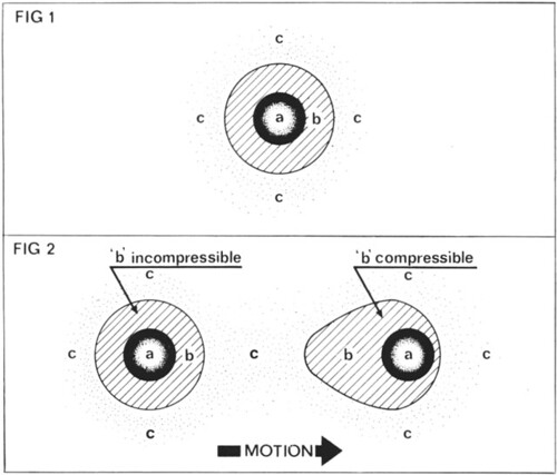 |
7.
| Therefore, let us assume that (b) is a sacrificial shield... One which is being replaced as a function of motion... (see fig. 3). In this manner the heat or radiated energy of the field (b)'s encounter with (c) is left behind the craft (a)... and is dissipated into the old sector of (c). |
9.
From assumption (3) motion was assumed from left to right. From assumption (4) the field (b) was assumed to be sacrificial. Let us now probe the mechanisms to produce these two assumptions. Referring to figure (4) the craft (a) is now fitted with a point (d) from which is emitted a dense, high-voltage, direct-electric current which makes its circuit through the field (b)... (actually forming the limits of (b). In conventional terms, the point (d) is negative with respect to point (e). The shell of the craft (a) is non-conductive so that the electric moment travels from (d) to (e) via the ambient medium (c) - which by virtue of the passing electric moment is captured as (b). Two factors will now produce motion to the right. The first is that the thrust from the accelerated fluid particles from (d) to (e) will produce a resultant to the right; and the second is that due to the Bernoulli Effect, the fluid pressure at right angles to the fluid flow from (d) to (e) is reduced;... in other words, a partial pressure reduction is formed to the right of line xy at right angles to the curved path of (de). Also, as a function of the fluid flow toward (e), from (d), there is a partial pressure increase at (e). This is caused by the collision of all the fluid particles from vectors in (dxe) with all the particles from vectors in (dye). 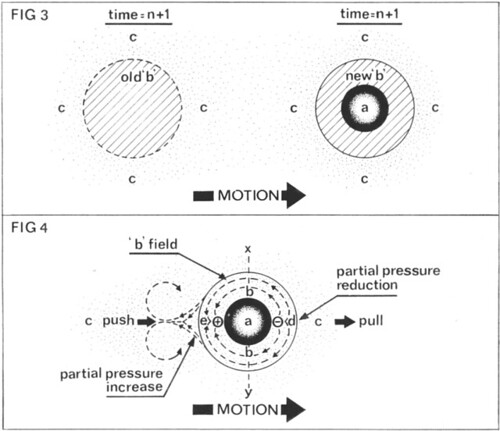 In figure (5) we see another side effect of this method of acceleration... At time (t=n), the craft and its field have pulsed a vector as shown by the dotted arrows. At time (t=n+1), the craft has moved to the right of its position at time (t=n), and the region (f) is rapidly normalising to a stagnant zone due to the vectors (see dotted arrows) colliding to generate heat and a little turbulence. In essence the craft has displaced an amount of fluid in front of itself and has moved into the space left by the displaced fluid, and has then replaced the same fluid in its original space after the craft, itself, has pulsed into the next zone. This phenomenon can be observed by watching a pneumatic tube in the older office buildings that still use them for shooting inter-office correspondence back and forth. They are sucked and pushed at the same time. A craft operating on such a principle would leave little (if any) turbulence; it would not be hampered by hightemperatures due to friction... (there would be none between it and (c) ); and it would not produce high-density shock waves as it passed through the wave velocity threshold of the medium... (the latter effect is caused because there are no forward vector components in the motion transfer to the right of line xy which eliminates the return inertial wave front that is normally encountered in the bruteforce, push-only methods of propulsion). |
11.
| If the craft is to travel in any other direction than to the right, then a method of navigational control has to be included in the mechanism. To determine a plane of orientation, a minimum of three points is required. For the ease of illustration, this discussion will use only three points... (bear in mind, however, that the more points on the navigational compass... the more accurate can be the navigational manoeuvre). Figure (6) shows four views of the craft with the three 'nav-points' attached to the left (or bottom) of the craft. Note that the left side of the craft has now been made concave. This has been done to optimize the partial pressure increase from the colliding fluid particles. Points (p), (q), (r) are variable resistors which are electrically connected to point (e). As the three points are all closer to point (d) in terms of the electric circuit, the electric circuit from (d) to (e) can be varied so that any one or all of the three points on the bottom can be made to draw more or less current than the other two points. Since the electric current transferring (and hence the fluid transferring) from (d) to (p), (q), (r) determines the partial pressure reduction on the leading surface, then the pressure gradient across the entire leading surface can be varied at will by simply varying the resistance at (p) and/or (q), and/or (r). var page_note_ratio = 1; For example, if the flow rate from (d) to (p) is 1000 fps; the flow rate from (d) to (q) is 1000 fps; and the flow rate from (d) to (r) is 1000 fps, then the partial pressure gradients over each of the portions of the surface controlled by one of the points arc equal to one another. Therefore, if, say, the resistance of circuit (d) to (p) is made higher than the resistance in the other two circuits, then the fluid flow rate from (d) to (p) would be less than the fluid flow rates of (d) to (q) or (r); and hence, the partial pressure reduction over (d) to (p) would be less than over the other two sectors. This would cause the craft to turn about a moment within the (d) - (p) sector... (see fig. 7). The effective lift or suction over the other two sectors would be greater than over (d) - (p), so the (d) - (p) sector would in effect look like a control surface (in vectorial function)... somewhat like a sail brake... when compared to the others. Until the flow rates are equalized again, the craft will continue to rotate as described. As soon as the desired attitude to the reference horizon is attained, then all flow rates are equalized and the craft whisks away... top first. |
13.
Notice that figure (8) shows the leading surface (the top) as a somewhat parabolic curve as opposed to the original hemispherical curve. The reason for the change is to direct more of the acceleration on the fluid at such an angle with the intended direction of motion as to obtain maximum lift for power consumed. If the shape of the surface were to be elongated more in the direction of intended motion, then the lift vectors on opposite sides of the leading surface would become more and more in opposition to each other giving less and less motion in any direction... (fig. 9). If, on the other hand, the shape of the surface were to be flattened in the intended direction of travel, then the angle for the travel of the electric moment becomes so acute that the charges bleed off into the medium... thus reducing the amount of partial pressure increase at (e) and also increasing power requirements drastically (fig. 10). An optimum curve has to be chosen depending upon a variety of intended or desired performance factors. 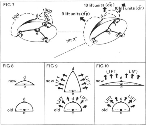 |
15.
| With such a unique method of motion comes another problem. Since the velocities attainable under such a relatively frictionless transfer process are excessive by modern concepts of safe structural velocities, a method of turning corners at speeds in excess of 20,000 mph has to be added to the mechanism of the craft. The same method must be added to the crew of such a craft to prevent structural fatigue. The method is almost too simple. The same electric field that traverses the surface of the craft can be used to polarise all masses within the limit of the field effect. In a conductor as the voltage and current frequency are raised over a certain value the current is observed to travel mostly in the surface of the conductor. This is commonly referred to as 'the skin effect'. Now in the craft the voltage levels will be in excess of 15,000,000 volts at frequencies up to 150khz... (more than ample to generate the skin effect). If the shell is a high-voltage semiconductor then the current will travel along the outside of the surface and even in the fluid medium in proximity to the surface. Once a current at such a high voltage is started in a particular direction the current tends to be very reluctant to turn sharp corners... because it is starting to have high inertial values. Since the crew and the entire craft are part of the circuit, whenever a direction change is made every molecule of the entire polarized (unified) field is accelerated at such a high rate of change into the new vector that the change appear, uniform, thus bypassing the problem of structural fatigue due to non-uniform inertial shifts. This means that the crew could be having morning tea break and the pilot could turn a corner at 25,000 mph without spilling a drop of tea. |
17.
| Partially due to hot spots in the shell circuit, and 'laminar fluid lock' at the boundary layer on the surface-to-fluid interface, a pulse rate has to be induced into the transfer circuit. For example, if the fluid flow rate were 1000 fps and the radius of the craft were such that the arc of the radius was 20 feet, then a pulse rate of 50 hz would give a circuit power wavelength of 20 feet or the exact length of the area (d) to the rim arc length. By peaking the power wave at the three points on the underskirting's periphery, the turn (or curl) in the wave can be quite readily conducted to area (e) by the three variable resistors. As the fluid flow rate increases, the field pulse frequency must increase to maintain the same wavelength. |
19.
| An effect that is the electrical equivalent of the "coriolis effect" that make, water swirl one way going down a drain will cause the electrical field transfers of the craft to form a vortex as it moves from top to rim to area (e). Also, due to ionization potentials of the particular fluid in which the craft is travelling, there may be visible evidence of the swirling vortex. It will make the craft spin unless contra-torque is applied to hold the craft stable... This contra-torque is supplied by the returning ions on the underside of the craft. (There is, however, a great deal of contra-torque available in the secondary, energy storage mechanism of the air turbine in the practical craft). |
PRACTICAL ION CRAFT
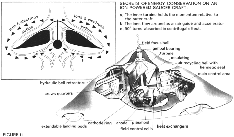
Let us now look at the practical craft. In figure (11) is a cutaway of the craft showing: the airflow, electric ion flow, field focus ball and rod, turbine tan, plasmoid ion source, field coils, cathode ring, directional anode, navigational ion collectors, landing rods, and crew quarters, etc.
There have been many attempts to fathom the workings of so-called "flying saucers". Some have actually discussed air flow mechanisms using ion accelerators. There has never been, however, a public report which showed the 'forbidden' (or unknown) secret... of how to maintain a high energy state device without a continuously equal high energy output per time.
Recall the case of the hot air balloon. It takes a certain amount of energy to heat the air inside the balloon. With 'proper' heat insulation, the balloonist can stay aloft for several hours on one heating. Does that sound like it takes a continuous high-density energy expenditure? Of course not.
What about the hydrogen-filled balloon... If released at ground level, it will rise to its 'specific gravitational' level. If taken from that level and drawn farther into space by a few miles and then let it go, what happens to it? It 'falls' back to its 'specific gravitational' level.
Even Leonardo da Vinci knew that. He once stated "Gravity comes into being when an element is placed above another more rarefied element. Gravity is caused by one element having been drawn into another element... A light thing is always above a heavy thing when both are at liberty. The heavier part of bodies is the guide of the lighter part."
If the craft and its field effect are viewed as a unit, then one will see that it has a more dense lower portion where the ions collide than it has in its upper portion... where ions are moving away from each other.
As long as the ion transfers follow that path, there will be a state of imbalance. To retain as much of the energy as possible when flying or hovering, it is necessary to keep part of the motion of the air with the vehicle.
This is done by using a centrifugal turbine fan which recycles part of the ambient medium... a manner of 'insulating' or containing the high-density energy source like the insulation in the hot air balloon).
This fan also cools the containing area for the high-energy-density plasmoid - which some people have seen as a dull red glow in the centre underside of their 'UFO's... and others have reported "...caused scorch marks upon landing." The three balls are landing pads in this version as it is necessary to have a certain distance between the ground and the underside of the craft to allow lift-off without taking great hunks of soil with the craft. The outer hull of the craft has positive and negative curve to compensate for the laminar turbulence (drag curls) that occur at higher velocities. The upper dome is movable vertically and even on a tilt to allow manual control of the recycled air. If the craft is to be sealed, the dome is simply dropped to form a sealed pocket. This of course means the energy expenditure from the field would have to increase to maintain altitude as the recycled air had been stopped.
The ball is vertically adjustable to change the effective voltage (charge distribution ratio) over the upper craft airspace and hence to change the field shape parameters.
The ball support shaft is heavily insulated to ensure proper charge distribution on the upper dome and also to effect the parameters of the field definition.
There are heat exchange vanes attached to the plasmoid's containing inductor to dissipate the excessive by-product heat.
Underneath the plasmoid are shown three coils aimed at the centre of the spinning plasmoid. There would be more of these in practice but for the simplicity of the theory, three are used to show how flight direction may be controlled by balancing the current between these three coils. If the plasmoid is tilted while spinning, the field throughout the entire craft and crew tilts with it. Also, the accelerated air ions assume a correspondingly new orientation.
This gives an electro-dynamic control function to the pilot which is infinitely better than those old-fashioned hydraulic systems. These field coils change relative strengths so fast that ultra high speed manoeuvres are exceedingly easy.
Just another short word on the charge path... The electric moment exits the craft at the ball; and since the voltage is so high the 'electrons' are reluctant to 'turn around and head back to the bottom of the craft.' There are some that enter through the upper portions of the craft's mass, but there are more that traverse the air to the lower third of the craft's mass before re-entry. This of course generates the air ion flow to the underside which in turn cools the plasmoid and recycles through the fan to exit from the upper dome to enhance the lift and thrust factors simultaneously.
If the craft is allowed to spin relative to the air and also to the fan, then high speed turns of thirty to forty "g's" can be 'amortized' over longer periods of time in the form of centrifugal spin... which counteracts some of the effect of being 'pushed' inwards toward the plasmoid in the momentary increases of field strength.
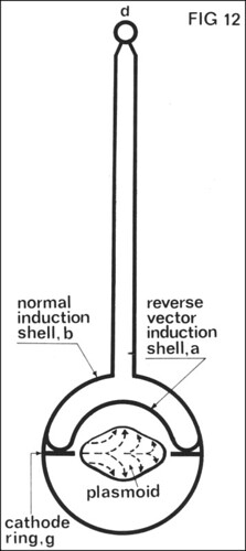
Communication to external sources can be effected in a number of ways; however, the most impressive is that one which modulates the field strength of the plasmoid with voice patterns. The broadcast covers a great number of radio frequencies simultaneously. In such cases 'receivers' can be the human mind all by itself. In figure (12) is a two-dimensional view of a three dimensional process. The spinning plasmoid induces an anti-vector current in the metallic (heat shielded) shell (a) which is a part of the metallic shell (b) (concentric). Because the current vector in (a) is against that of the plasmoid's, it does not 'short-out' into the plasmoid.
The reverse vector current flows up and into (d) where it is passed to the air, then to its collectors (e) and to the normal induction shell (b)... which is also connected to the (a-b) shell as shown.
Remember that, the entire craft and crew are a part of the circuit. These voltages and relatively high frequencies develop a 'skin effect' all over the outside of the craft. Even though the crew are in the field, the current flow is in the outer surface because the internal charge crowding acts as an 'insulator'.
No dielectric is necessary in the craft, as the current vectors act like 'phase-locking' loops.
Try to visualize the following:
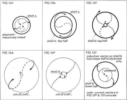
1. In figure (13-a) the top view of the plasmoid shows the old current vector (dotted arrow) and the new current vector in shell (a) (solid arrow)
2. In each successive, step the current vector is shown in its new stage versus its last.
3. At stage (13-c) the current is anti-vectored exactly to the original current in the upper plasmoidal hemisphere (fig. 13-a, Shell a),
4. In figure (13-d) the current has curled under the wing surface,
5. In figure (13-e) the current has joined the induced anti-vector current from the lower half of the plasmoid (see fig. 13-f) to complete the circuit.
Throughout this exercise in building a hydrodynamic craft the fluid has not been called 'air' for the simple reason that this craft can sail in air, water, or even the fluid of space (often referred to as 'the ether or the fine structure or the quanta sea'). By varying the frequency, power, and voltage levels on an electro-dynamic craft, so-called 'anti-gravity', invisibility, and light-speed translation from point to point are now conceivable. Gravity has frequency... but that is another discussion all unto itself. Another discussion will detail the process for generating and storing extremely high voltage power in the form of plasmoids... (or self-containing plasmas), voltage transforming capacitors, and the rudiments of wireless broadcast of electricity to users around the entire planet... through the use of overlapping VLF standing wave power broadcast network.
Time permitting, this author will later release his papers on the order and origin of electron 'shells' and planetary orbits as functions of convergent and divergent vortexial wave forms in 'fluid space'. As a clue to those who would be interested in such a discussion, the reason that electron shell orbital radii do not apparently follow a progressively greater dimension outward from the nucleus is that they are the sum of two opposed progressions; one toward the nucleus (as a space-reflected, inertial wave form) and one away from the nucleus (as an energy-centre reflected inertial wave form). These papers will discuss the application of resonating magnetic fields to use the magnetic fields of the Earth and any other rotating magnetic body as not only sources of energy, but also new means of propulsion.
From The Cosmic Conspiracy - see more @ http://nexusilluminati.blogspot.com/search/label/stan%20deyo
See PRELUDE to ACTION: Introduction to the Cosmic Conspiracy @ http://nexusilluminati.blogspot.com/2011/01/prelude-to-action-introduction-to.html
Einstien's Relativity Error @ http://nexusilluminati.blogspot.com/2009/09/einstiens-relativity-error.html
For further enlightenment enter a word or phrase into the search box or click on any tag (at the bottom of the page) @ New Illuminati:
And see
The Her(m)etic Hermit - http://hermetic.blog.com
New Illuminati – http://nexusilluminati.blogspot.com
New Illuminati on Facebook - http://www.facebook.com/pages/New-Illuminati/320674219559
This material is published under Creative Commons Copyright (unless an individual item is declared otherwise by copyright holder) – reproduction for non-profit use is permitted & encouraged, if you give attribution to the work & author - and please include a (preferably active) link to the original along with this notice. Feel free to make non-commercial hard (printed) or software copies or mirror sites - you never know how long something will stay glued to the web – but remember attribution! If you like what you see, please send a tiny donation or leave a comment – and thanks for reading this far…
From the New Illuminati – http://nexusilluminati.blogspot.com
No comments:
Post a Comment
Add your perspective to the conscious collective