The Nassikas Superconducting Lorentz Thruster:
Levitation with essentially zero power draw
and heavy payload capability
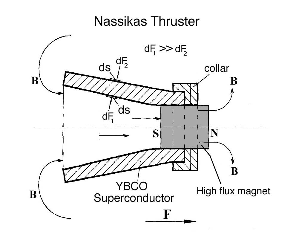
The Nassikas Thruster (version 1)
by Paul
LaViolette
A previous posting on this site discussed the first version of the Nassikas reactionless thruster, shown above, which consists of an YBCO superconductor casting shaped in the form of a nozzle with a permanent magnet secured within its throat. Dr. Nassikas received a U.S. patent on this version last year (US 8,952,773).
That posting described tests which showed that this Nassikas thruster I (version 1) exhibited a thrust-to-mass ratio 1000 times greater than the NSTAR neon ion thruster used to propel the Dawn spacecraft. It is also found that it even out performs the Q Thruster (or EMDrive), a reactionless thruster that NASA is currently researching for possible future deep space missions. Not only does the Nassikas thruster I have a thrust-to-mass ratio 10 times greater than the EMDrive, it also achieves its thrust with zero power input. The EMDrive, on the other hand, requires 1 kilowatt of power for every 30 grams of force (0.3 Newtons) it delivers.
But in this posting we would like to announce a new superconductor thruster idea that Dr. Nassikas has come up with which should be able to produce 30,000 to a million times more thrust than his previous version. The implications of this new thruster invention are mind boggling. To distinguish it from his earlier version, he refers to it as the Nassikas thruster II (version 2); see image below.
The Nassikas Thruster II
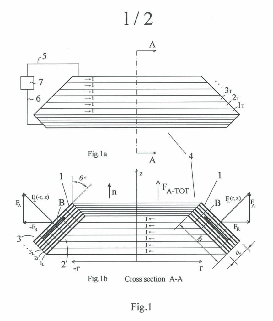
The Nassikas Thruster
(version 2)
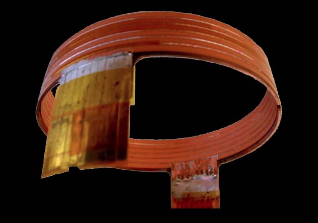
Figure 2. Artist’s conception of the Nassikas thruster-II
conical superconducting coil.
The Nassikas thruster-II is basically a superconducting coil that has a slight taper so that it has the form of a frustrated cone, rather than a cylinder; see diagram above. The coil is wound from high temperature superconducting tape such as REBCO CC (conductor coated) tape; see windings 1, 2, 3, etc. in Fig. 1a. When energized with an electrical current from an energizer (7), a very high amperage current begins to flow in the coil windings and this generates a strong magnetic field oriented essentially along the coil’s axis and in the plane of its windings.
The superconducting layer in the REBCO CC tape windings is very thin, on the order of 1 micron. Hence the magnetic field will penetrate this layer and will interact with the high current flowing there. This interaction produces a very strong force called a Lorentz force, which is oriented at right angles to both the direction of the current and the direction of the magnetic field; see outward pointing arrow FL in Figure 1b. This Lorentz force phenomenon is very standard physics, something that any physicist or electrical engineer will agree exists. Also it is something that designers of superconducting coils are very wary of because if this outward pushing force is too strong it can rip the coil apart.
Superconducting coils are normally wound as cylinders; hence their Lorentz forces necessarily push radially outward on the sides of the coil. Since the forces on opposite sides of the coil oppose one another, the result is only to produce a stress on the coil that attempts to radially expand it, but which is counteracted by the tensile strength of the coil’s windings. This is something known by all engineers who wind superconducting coils. However, in the case of the Nassikas thruster, the coil is conical rather than cylindrical. Hence there is a Lorentz thrust component resultant directed along the axis of the coil in its vertical direction toward the coil’s narrow end; see force vector FA in Fig. 1b. Because there is no opposing force to counterbalance this force, the coil should develop a net upward thrust that should propel it upward. This should not manifest merely as a static stress in the coil itself, but should be capable of actually levitating the coil.
We initially need $32,000 to build a prototype coil and test it. To raise this money, we are currently running a crowdfunding campaign on the Indiegogo website and hope you will contribute to our project. With enough help we can make this happen. Our page may be found at: https://igg.me/at/levitation-thruster.
The test coil we intend to have made will have an outside diameter of 16 centimeters (6.3″) and a taper of 3°. Since the purpose is only to demonstrate the coil’s ability to produce a propulsive thrust, we are designing it with fewer windings than would be used in a marketable version. Computer calculations performed by the prospective coil manufacturer show that at liquid nitrogen temperatures, with a current density of 70 amperes per square millimeter flowing in the coil windings, the coil should produce a magnetic field in the vicinity of the coil windings having an intensity of about 0.3 Tesla. This is about the same magnetic field strength as that produced by a strong refrigerator magnet. Still, Lorentz force calculations indicate that this low-thrust test prototype should generate a propulsive force of 66 kilograms at liquid nitrogen temperatures. The coil together with its glass dewar flask filled with liquid nitrogen should weigh about 5 kilograms. Hence it should produce a levitation force 13.6 times greater than its weight! In other words, a group of these thrusters could easily lift a vehicle off the ground. This thrust-to-weight ratio is about 9 times that of the Space Shuttle main engine! A more practical production version should be capable of generating thrusts even 20 times greater at liquid nitrogen temperatures. At liquid helium temperatures, we estimate this test coil should generate even far greater thrusts.
Remember the above calculations are based on standard physics (the cross product of current and magnetic flux density). So even if our test shows that these computer model calculations have been overly optimistic even by a factor of ten, it should still be possible to produce more powerful versions that have the capability of levitating a heavy payload.
For our test we intend to have the thruster and its dewar suspended by a cord from the laboratory ceiling. The thruster coil inside the dewar would have its axis oriented in a horizontal position. So once cooled down and energized it should produce a lateral force. We will measure this force with an electronic balance oriented sideways so that the dewar and its coil would exert a force on the balance, the force being transferred through a rigid styrofoam spacer block. We plan to first measure the force developed when the coil is immersed in liquid nitrogen (77° Kelvin temperature) using a light weight dewar. If the coil shows an over unity thrust-to-weight ratio, we plan to test it in a vertical orientation to show that it can levitate. Then, if the liquid nitrogen test is successful and if funds allow, we plan to conduct a similar test with the coil immersed in a larger liquid helium dewar (4° Kelvin temperature). As mentioned above, the expected propulsion force in this case should be one hundred fold greater.
The Nassikas thruster-II technology, could make the following possible:
• Cars that could take off vertically and fly through the air.
• Cruise ships that could levitate as in the movie The Fifth Element.
• Space shuttles that could lift off the Earth without the help of rockets.
• Shuttles that could fly to Mars in 5 days, not 9 months as NASA currently has in mind.
• Ships that could attain near light speed velocities and travel to the nearest star system (e.g., Proxima Centauri) in 4.5 years, instead of 20,000 years.
• Scooters that could not only move forward, but hover and fly above the ground.
• A “hoverboard” something like that depicted in the movie Back to the Future which the movie predicted would be in common circulation in the year 2015.
• Lorentz thruster motors that would produce shaft torque for generating electricity.
This technology would be essentially pollutionless requiring only the production of a small quantity of liquid nitrogen or liquid helium to make it work. Hence its carbon footprint would be virtually insignificant compared to the petrol guzzling technologies currently in use.
Historically, social advances have been brought about by technologies that either improved transportation (moved people or goods more efficiently from one place to another) or improved on energy production. This technology should do both. If it works as expected, it would bring untold prosperity to the world.
Some may be thinking that this all sounds too good to be true, maybe even crazy. Well it does require that we change some of our concepts about what we think is possible. Remember that many thought that the Wright brothers were dreamers until their air flight at Kitty Hawk.
The Nassikas Thruster-I: A Low Thrust Precursor
The Nassikas thruster-II invention was inspired following the successful results obtained with its low thrust precursor, Nassikas thruster-I. The two thrusters operate on a similar principle. So given that the Nassikas thruster-I has been shown to work, we strongly believe that the Nassikas thruster-II should work as well. Pendulum tests of the first version have been witnessed on various occasions by two Cambridge University physicists, one of whom is a Nobel Laureate, as well as by five Athens university physicists. Excerpts of some of these pendulum tests are presented below.
Professor Nassikas has explained the design of his conical superconducting coil and its means of generating thrust to one of the primary Ph.D. engineers working at the NHMFL Mag Lab (National High Magnetic Field Laboratory) in Gainesville, Florida, an expert in superconducting coil design, who agreed that it may very well work as Dr. Nassikas claims. We have also informed NASA personnel associated with the NIAC program (NASA Innovative Advanced Concepts program) about both of these thruster designs and their capabilities and one member of that team was interested enough that he requested that we keep him informed of our progress. This thruster concept was also described this past October (2015) in a lecture presented at the Secret Space Program Symposium in Texas, and it generated considerable interest.
Although the thruster would produce less thrust at liquid nitrogen temperatures, as compared with liquid helium temperatures, we expect it will be more than enough to get a payload off the ground. Moreover liquid nitrogen is more economical to use since it is about 50 times cheaper and also is available in most towns at nitrogen fill up stations used by refrigeration trucks. For those interested in the hoverboard application, the Nassikas thruster hoverboard would first need to be fueled up with liquid nitrogen and then the coils would need to be energized to get their current circulating before the hoverboard would be ready to use. However, once energized, the Nassikas thruster-II needs no power source to operate since superconducting coils operate with essentially zero resistance. As long as the coil remains immersed in its liquid nitrogen coolant, its current would circulate indefinitely, all the while generating an upward thrust. In designing any flying vehicle, whether it be a hoverboard, car, or larger ship, it would be a good idea to design the vehicle with three thrusters in triangle formation and gimbaled so that they could be angled to regulate the amount of upward thrust. Also one would want to include a gyroscope to stabilize the vehicle’s orientation.
Once this technology is proven successful, manufacturers would likely first be applying it to vehicle propulsion and space propulsion. As mentioned, one advantage of these superconducting thrusters is that once they are energized they should maintain their Lorentz force propulsive thrust without further energy input. The only cost would be the need to periodically fuel up with liquid nitrogen coolant at ten cents per liter (or $5 per liter if a liquid helium coolant is used). Of course no coolant would be needed in space since behind a sun screen the temperature there is about 40 degrees above absolute zero, and even lower as you get further from the Sun. Hence trips could be made to Mars and beyond with virtually no energy input requirement.
Some may be wondering whether it is possible for something to move and produce useful work without requiring any physical source of input energy. Doesn’t this violate some laws of physics? Well, the same could be said about the Nassikas thruster-I which we have demonstrated does just that. It generates a thrust without any source of physical energy input. This has been demonstrated numerous times in pendulum tests.
How the Nassikas Thruster I Produces Its Thrust With No Power Input
We will discuss below where the paradigm busting Nassikas thrusters might be getting their energy. But first let us review how the version-1 device develops its thrust. To understand how the Nassikas thruster-I works, we must first learn about Meissner forces, a subject which is standard physics. When a superconductor is cooled below its critical temperature (e.g., by immersing it in liquid nitrogen), it impedes external magnetic fields from entering its interior. That is, “super currents” are generated within the superconductor which produce a mirror field that repulsively opposes any external magnetic fields. This repulsive force has been called the Meissner effect force. This is the force that levitates maglev trains. That is, the superconductor plates on the bottom of a maglev train repel the upward pointing magnetic field produced by magnets embedded in the rail and as a result the train is made to float above its track.
Now, what Prof. Nassikas has done is find a way of attaching the magnet to the superconductor and thereby producing a net propulsive force which allows the “train” to leave its tracks and travel anywhere it wishes to go. The “secret” behind this is that his thruster is able to produce unbalanced Meissner forces. Referring to the figure at the top of the page, it is seen that the magnetic field from the attached permanent magnet surrounds the superconductor nozzle producing Meissner effect forces both on the surface within the nozzle’s throat as well as on the nozzle’s exterior surface. These forces, however, are unbalanced. Because the magnet’s lines of flux are more concentrated in the nozzle’s throat, the outward directed forces dF1 pushing against the nozzle interior will be much greater than the inward directed forces dF2 pushing against the nozzle’s exterior surface. Hence dF1 >> dF2. As a result, when all these opposing force components are accounted for, it is found that a net resultant force remains which is directed toward the nozzle’s narrow end. It turns out that this resultant force is able to displace the nozzle as a whole, i.e., cause it to accelerate. These is not a stress force acting within the superconductor, this is a true propulsive force.
In other words, although the permanent magnet is creating this magnetic field, the magnetic field itself is not rigidly attached to the magnet; it resides in the space around the magnet and the superconductor and is able to act in a manner free of attachments to this magnet. As a result, the net Meissner effect force it produces on the superconductor is able to propel the superconductor relative to the instantaneous space reference frame. As the superconductor moves forward, so does the attached magnet and the Meissner-effect-generating magnetic field. So, if left free in space where temperatures are cool enough to keep the thruster in its superconducting state, the thruster should accelerate indefinitely.
Now some physicists might complain, does this not violate the law of energy conservation? Where does the energy come from that propels the thruster? Dr. Nassikas maintains that it comes from quantum space-time itself, from what physicists call the quantum vacuum. He has explained this in various publications listed in the reference section below. In effect, the Nassikas thruster taps into the quantum vacuum prime mover that exists throughout space. Nikola Tesla would have referred to this as “harnessing the wheelwork of Nature”. [I’ll give an explanation from the subquantum kinetics viewpoint further on below.]
Furthermore one must realize that when it comes to imposing the standard teachings of physics, the subject of how superconductors interact with external fields constitutes a gray area. Currently a unified theory does not exist that describes what happens both outside a superconductor as well as inside. Physics relies on Maxwell’s equations to describe field phenomena outside a superconductor and on the London equations to describe phenomena occurring in the thin outer layer of the superconductor within the “London penetration depth”. Deeper than that we have no theories and no unified theory to tie all this together. So if anyone claims that the Nassikas thruster can’t possibly work because it violates “known laws of physics”, they are standing on relatively thin ice. Moreover we have the pendulum test results to prove they’re wrong.
By comparison, the Nassikas thruster-II also produces its thrust with no energy input, but the principle behind it is virtually the same as in the version I thruster. In both cases you have unbalanced forces acting on superconductors having a conical geometry and in both cases these forces are produced by magnetic fields interacting with electrical currents within the superconductor (supercurrents induced within the superconductor nozzle in version-I versus strong currents energized within a superconducting wire coil in version-II). The end result is the same: propulsion toward the nozzle’s narrow end, or toward the coil’s narrow end.
Over-unity Energy Phenomena from the Subquantum Kinetics Perspective
Many years back I wrote a paper protesting the penchant for physicists to ubiquitously apply the First Law of Thermodynamics (the energy conservation law) to all physical phenomena. For example, read: http://www.starburstfound.org/downloads/physics/IECEC.pdf. I show, for example, that astronomical and cosmological evidence calls this practice into question. Namely, the First Law may be fine to explain the workings of a refrigerator (as was its initial purpose), but any extension of this rule to other physical phenomena should be held accountable to standard test, not merely accepted on faith.
Also I encourage people to visit the following website link: http://www.etheric.com/Electrogravitics/maglev.html which shows that the well known phenomenon of maglev, used in the operation of super fast trains, actually violates the First Law. This presents a video showing a simple experiment that one can perform which demonstrates that work is expended during the onset of Meissner effect repulsion (magnetic levitation) with there being no visible source of energy input. Physicists know about this, but remain silent about it.
The best reference for the subquantum kinetics view on over-unity energy production phenomena is the following paper: http://starburstfound.org/reality-overunity-generators-evidence-open-system-universe/. To summarize from this paper, all over-unity “free-energy” phenomena, including the Nassikas thrusters, cease to be a mystery when we come to realize that there is something more to existence than just the physically observable world. To find out more about this paradigm, read my book Subquantum Kinetics or some of my related journal papers.
According to subquantum kinetics, our universe is not a “closed system” as physicists have long led us to believe, but an open system. How can I say this with some certainty? Namely, I have shown that by positing the subquantum kinetics paradigm with its Model G ether reaction scheme, one is able to explain most all of what standard physics theories attempt to explain and a lot more of what they hadn’t explained. All of this has been verified through repeated a posteriori observational confirmations.
So what energy source drives the propulsive force of the Nassikas thruster-II? The very same subquantum flux that sustains the very matter of our bodies and the chair that we sit upon. The bottom line is that we live in an open universe in which material particles and photons are continuously created and sustained by this underlying flux. So issues of where the energy ultimately comes from should not trouble us. It comes from Space itself considered in its higher dimensional perspective.
As to how can the Nassikas thruster coil generate a reactionless thrust? Standard physics would suppose that the magnetic field that the coil produces is somehow attached to the electrons that produce it and that these electrons are in turn confined in the coil’s winding. Hence they would assume that any Lorentz forces produced by the interaction of this magnetic field should merely react back on these electrons and merely produce stresses in the coil. Subquantum kinetics, however, maintains that the magnetic field is seated in the ether and that it itself has no mechanical attachment to the electrons that produce it. Moreover there are experiments that one can point to that substantiate this, such as the Faraday disc experiment. Hence the Lorentz forces exerted on the coil are exerted relative to the coil’s surrounding ether, relative to its local inertial frame. Therefore they are able to propel or accelerate the coil relative to this instantaneous inertial frame. Simply by shifting our conceptual perspective, the reactionless thrust of the Nassikas thruster becomes something that is now understandable.
Our Crowd Funding Project Could Transform the World
Few technologies literally transform the world. Examples include the invention of the wheel, the development of the automobile, or the creation of the internet. It is very likely that the Nassikas Thruster will become one such technology. The experiment we plan to do with your crowd funding support, solicited at: https://igg.me/at/levitation-thruster, will determine if our theoretical predictions are correct. Of course, if successful, the Nassikas thruster-1 would be rendered obsolete since the test thruster we are planning to build is expected to develop 30,000 to 100,000 times more thrust. So, rather than just sending instrument probes to Mars and Ceres, with the Nassikas thruster II technology we would be able to send manned space shuttle missions to these and other solar system destinations. Moreover trips to nearby stars could become a real possibility.

References
LaViolette, P. A. Secrets of Antigravity Propulsion. (2008, Bear & Co., Rochester, VT) [For general background on the history of reactionless thruster technology.]
LaViolette, P. A. Subquantum Kinetics. (2013, Starlane Publications, Niskayuna, NY).
Nassikas, A. A. “Magnetic propulsion device using superconductors.” U.S. patent No. 8,952,773, February 10, 2015.
Nassikas, A. A. “Minimum contradictions physics and propulsion via superconducting magnetic field trapping.” AIP Conf. Proceedings, 1208, pp. 339-349, 23-25 February 2010. Space, Propulsion & Energy Sciences International Forum SPESIF‐2010: 14th Conference on Thermophysics Applications in Microgravity 7th Symposium on New Frontiers in Space Propulsion Sciences, 2nd Symposium on Astrosociology, 1st Symposium on High Frequency Gravitational Waves. Abstract published at SAO/NASA.
Nassikas, A. A. Experimental verification of superconducting self propulsion.” Proceedings of the Natural Philosophy Alliance, Albuquerque, 2012.
Nassikas, A. A. Minimum Contradictions Everything, Reviewed and edited by Duffy, M.C. and Whitney, C.K., Hadronic Press, p. 185, ISBN: 1-57485-061-X, 2008. Available through Amazon.
From The Sphinx
Stargate @ http://etheric.com/nassikas-thruster-ii/
For more information about antigravity systems see http://nexusilluminati.blogspot.com/search/label/antigravity
- and see 'older posts' at the end of each section
- Scroll down
through ‘Older Posts’ at the end of each section
Hope you like this
not for profit site -
It takes hours of work every day by
a genuinely incapacitated invalid to maintain, write, edit, research,
illustrate and publish this website from a tiny cabin in a remote forest
Like what you see? Please give anything
you can -
Contribute any amount and receive at
least one New Illuminati eBook!
(You can use a card
securely if you don’t use Paypal)
Please click below -
Spare Bitcoin
change?
For further enlightening
information enter a word or phrase into the random synchronistic search box @
the top left of http://nexusilluminati.blogspot.com
And see
New Illuminati – http://nexusilluminati.blogspot.com
New Illuminati on Facebook - https://www.facebook.com/the.new.illuminati
New Illuminati Youtube Channel - https://www.youtube.com/user/newilluminati/playlists
New Illuminati’s OWN Youtube Videos
-
New Illuminati on Google+ @ For
New Illuminati posts - https://plus.google.com/u/0/+RamAyana0/posts
New Illuminati on Twitter @ www.twitter.com/new_illuminati
New Illuminations –Art(icles) by
R. Ayana @ http://newilluminations.blogspot.com
The Her(m)etic Hermit - http://hermetic.blog.com
DISGRUNTLED SITE ADMINS PLEASE NOTE –
We provide
a live link to your original material on your site (and links via social
networking services) - which raises your ranking on search engines and helps
spread your info further!
This site
is published under Creative Commons (Attribution) CopyRIGHT (unless an
individual article or other item is declared otherwise by the copyright
holder). Reproduction for non-profit use is permitted & encouraged - if you
give attribution to the work & author and include all links in the original
(along with this or a similar notice).
Feel free
to make non-commercial hard (printed) or software copies or mirror sites - you
never know how long something will stay glued to the web – but remember
attribution!
If you
like what you see, please send a donation (no amount is too small or too large)
or leave a comment – and thanks for reading this far…
Live long
and prosper! Together we can create the best of all possible worlds…
From the New Illuminati – http://nexusilluminati.blogspot.com


