The Pyramid Pump
How the Great Pyramid functioned as a Water Pump

Below is a greatly simplified animated diagram and explanation of how the Great Pyramid pumped water. The position of the upper diagonal has been reversed to better clarify how the pump works. However, the shape of the Pyramid will not permit such an arrangement of the various mechanical elements. There are a great many refinements and complexities that will not be address in this short and abbreviated explanation.
The lower diagram is an image map that will direct you to areas of interest. From there you will find information of greater detail and depth of the function of each pump component. There is also a very helpful FAQ Page that answers specific and general questions about this material.
Take a moment and watch the action of the pump. It is very unique and deserves a little time to get a feeling for how each part relates to the rest of the pump. Below is an image that divides the pump into its components.
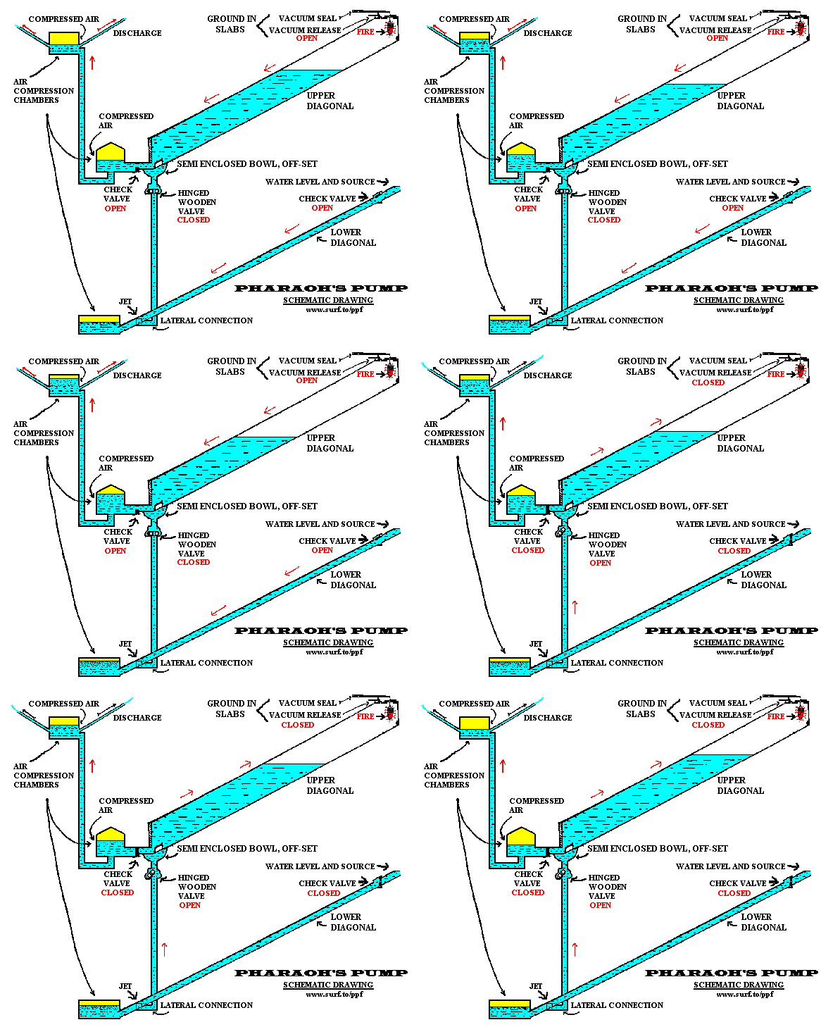
Although the Great Pyramid is a pump, it doesn't look or operate like any pump people are familiar with. This pump is powered by FIRE. This fire is located at the top of the Grand Gallery. There is still a very distinct aerodynamically shaped soot patter indicating the location of this fire. The combustion of fire creates a partial vacuum in the upper area of the airtight Grand Gallery. The result of this partial vacuum is water is raised up the Grand Gallery. The fire does not "go out" during each cycle. When the oxygen in the upper part of the Grand Gallery is consumed, the fire smolders until the next cycle is started.
The above two forces move the water up the Grand Gallery!
After the water has risen in the Grand Gallery, the vacuum release valve, (located at the top of the Grand Gallery by the fire) is opened, releasing the partial vacuum created by the fire. This allows fresh air to be introduced into the area above the water and causes the water to move down the Grand Gallery. This repeated cycle of raising and lower this ponderous column of water is analogous to the movement of a piston back and forth in a cylinder!
The opening of the vacuum release valve at the top of the Grand Gallery starts the downward cycle.
The highly compressed air in the upper part of the Queen's Chamber forces water up into the King's Chamber. The discharge tubes in the King's Chamber are located in the wall about 5 feet high. Above that, air is compressed by the water coming from the Queen's Chamber. This compressed air in this secondary chamber forces the water out the discharge tubes.
The use of highly compressed air is the force used to move water above the column of water in the Grand Gallery.
Select the area you want for more detailed information.
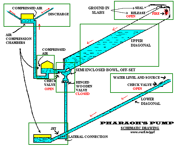
Don't just say that it won't work! The truth is that at one time it did. Some of the information is technical but not incomprehensional. Click on each area and see how it relates to the complete system. Check out the FAQ Page and if you have a question or comment let us know!
How the Great Pyramid was Built
Based on the information and discoveries of Edward Kunkel
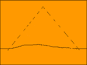
Before the Great Pyramid was built, the site was a granite outcropping or rock or whatever you want to call it. The shape and size of this outcropping before the building of the Great Pyramid is unknown. In the finished pyramid the granite outcropping protrudes up to a height of at least near the bottom of the Queen's Chamber. The site is on a gradual sloping hillside. Uphill form the Great Pyramid is the Libyan Desert.  Almost all agree that the two subterranean shafts and the subterranean room were excavated before the pyramid was built. The simple drawing below shows the state of construction when the subterranean shafts and chamber are completed. It is the contentionof the Pharaoh'sPump Foundation that the ineffective barriers in the passages were in reality valves of various types. These check valves are described elsewhere in this site. IF the dead end shaft that leads from the Subterranean Chamber is a drain with a valve placed in it, then all the elements of a hydraulic ram pump exists, in gigantic proportions! Here is what Mr. Kunkel says about this Subterranean area. The mechanical element needed to make the Subterranean cuttings a water pump is a drain and valve. The mechanical element? - A dead end shaft, cut in the south-eastern corner of the compression chamber. It is 52 feet 9 inches long, 2 feet 7 inches wide, and 2 feet, 5 inches high. Its direction is from true north to south. Its position is horizontal. It lies at the lowest corner of the chamber. Its position suggests that it could be a drain: but it dead ends in the rock. Even though it is 105 feet below the base of the building; it is still high enough from the outside to function as a drain. Apparently this dead end has never been examined; with the idea in mind, that it may be a drain duct. In 1954, two sun ships were discovered in the rock hewn cavity at the very southern base of the pyramid. It is reasonable to assume that the size and shape of this cavity has been surveyed and recorded. But, such data is hard to come by; at least for me. It would be interesting to examine the north wall, and ascertain the distance from it to the terminus of the dead end. The terminus of the dead end is about 83 feet south of dead center of the building. This leaves a space of about 300 feet to its southern base. In short, I believe there exists a connecting duct, between the dead end, and the sun ship cavity. Explorers might hit pay-dirt; if they take a good hard look, at the end of the dead end, and the north wall of the sun ships crypt. The cutting of this shaft must have been an awful job. - It is so small. . . . It is only 29 inches high, and 31 inches wide. - There is very little elbow room. - Maybe a midget crew cut it. I'll never believe that its existence is due to over-sight, or gross error. - I'll never shrug it off, as a miscalculation. I have too much respect for the ancient engineers for that. Why all the fuss and to do about a hypothetical water duct? If such a duct were discovered; what possible mechanical significance would be interpreted from it? Another question; What if no waste mechanisms were found in the duct? The answer lies in this simple fact; a waste duct in this particular area, would be definite proof that the engineers had cut a simple water ram in the solid rock. A simple water ram of monstrous proportions. A ram, which pumps for more water than it wastes. My guestimate? At least 40 tons for one ton of wastage to a height of 60 feet; during a time cycle of one minute. Answer; the sun ship cavity itself may be part of it. My line of reasoning follows this pattern. Primarily the cavity was cut for use. After it was no longer needed, the sun ships were installed. Why not decorate it, touch it up a bit, with some regal trappings? What if no duct were found at all? - I'd say they overlooked a good bet. - My alibi in this case; they learned they didn't need it; which after all, does not make a bit of sense. I have believed from the very first, that this tube is part of a drain, and that its outlet is sealed, in just as clever a fashion as the ancients managed to conceal other openings. It is utterly fantastic to believe, that the ancient engineers overlooked this common device; a drain that can be opened and closed at will, and thus; employ the same mechanics of the common ram. What will the drain valve look like? - It will be a "door with pivots." We call them butter-fly valves. They are easy to open and close, and are operated by a handle. Pairs of holes with proper seats to fit this type of valve are found in the tube, leading to the upper diagonal. - And none, for a moment doubt, that these seats and holes are for this type of, "door." A short distance down in the solid rock of the lower diagonal, is a tiny offset, "wherein," says Petrie, "hung a door that swung inward." A pair of eight inch round holes are found here, one in the ease wall and the other in the west wall. Adjacent to these round holes, is granite masonry. Giving this mechanical element an interpretation in hydraulics, is, check-valve. The holes support a round shaft, and the granite masonry is the valve seat. End of excerpt The underground cuttings were used as a pump. They were doing what every engineer must do before he undertakes such a project. The machine comes first, and in this case it was a water pump. These subterranean cutting formed a hydraulic ram pump. Now we will look at: How the pump was used to BUILD the Great Pyramid! All of the subterranean passages and subterranean valves are finished and the colossal hydraulic ram is ready to go! If the hydraulic ram pump pushes water up the central shaft it will be wasted because the water will just flow down the hill side. At this stage parabulious walls were built around the building site. This created a catch basin for the water. Below is a view of the parablious wall in place with the catch basin filled. Near the base of the Great Pyramid, to this day can be seen “parabolus walls” made of earth, which surrounded the building. The walls form a rectangular basin. It looks like the remains of an ancient catch basin, or reservoir. And the 14 foot vein of river silt, which is found in it, is mighty convincing evidence, that in ancient times, this rectangular enclosure held water, and formed a pond 180 acres in area. And the little rocky knoll, upon which the pyramid stands became a little rocky island. The engineers had already built a pump. The next step is to build a device to use it, otherwise pumped water would pour down over the sides of the knoll, and be wasted. Try to envision if you will, the rocky knoll, high above the Nile, before a single block was set. It must have been a bleak, bare, gray mound of limestone. It was not flat. It must be leveled off. To use the water, it must be caught. The simplest device to catch it is a ditch. Once a ditch was cut and filled with water, it formed a perfect device for a leveling operation. Water would pour from the ditch at the lowest contour of the rock. This lowest contour determined the elevation of the base. Five hundred chiselers could be put to work at one time, and whack the base down to a uniform level, P.D.Q. The still water, in the ditch would be their gauge, and simplify surveying operations.  With simple water control devices installed in the ditch, the 16 ton casing stones, these precision cut, beveled beauties, could be floated on a barge with brackets on the side; Brackets not unlike the modern fork lift, and lowered gently into place for a long, long rest. For countless centuries they have evoked the awe, the admiration, and conjecture of all men. With profound silence, they have cried out through the ages, the glory of a vanished race of artisans, engineers, scientists and kings. But how did the Ancient Engineers get the blocks up to the site of the Great Pyramid? |
At this point in the construction, the base had been leveled using water as a guide. Everything was ready for the first row of casing stones to be set in place. How would YOU bring 16 ton stones from across the river that are already on barges to the site of the Great Pyramid?
Evidence indicates that a series of locks from the Nile to the building site were created to move the stones up from the river to the building site.
These series of water locks brought the first level of casing stones up to the site. The locks worked just as the water locks work in the Panama Canal. The subterranean cuttings which are a colossal hydraulic ram supply the needed water for the locks.
Note about above image: No, it is not to exact scale, it is just a simple computer image to get the ideas of this stage of construction clearer. No, the image is not a perfect representation of the exact placement of every element of this stage of construction but it should help give an idea as to the process of construction. If you are an artist and would like to make a series of illustrations to replace these primitive ones, let me know.
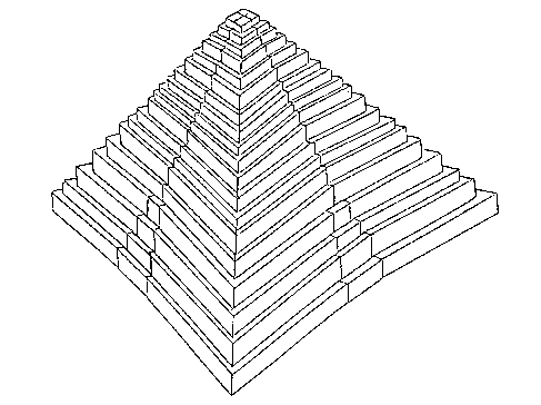
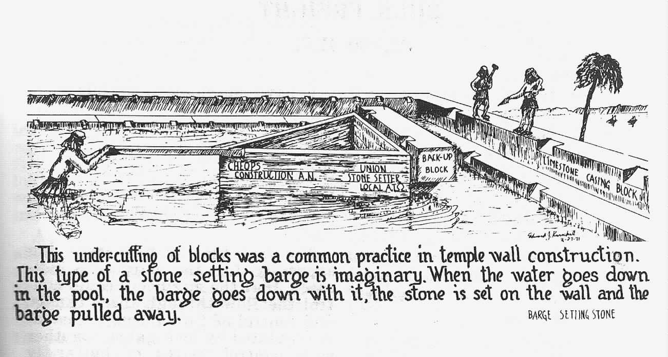
The handling of such huge precision-cut masterpieces, demands absolute control of the handling medium. - This fact is a superlative, MUST. If a rectangular trench were cut inside the casing stone base, so as to form a moat, the base would then resemble, a tow-path alongside a canal. A barge with brackets on the side to carry the block could be floated to location in the moat; then lowered into place by draining the moat. Thus; a 16 ton block could be moved and set; as gently as mother lays a sleeping babe in a crib.
After the ditch was filled, the builders could move stone laden barges freely about in the pool, and go about their Pyramid building in a big way.
The completion of the first course of casing stones formed a rectangular enclosure, in which water could be impounded, and the bottom of the moat became a foundation for the back-up blocks.
Another translator of Herodotus offers this translation.
"They made it first in the shape of stairs, and lifted up the stones that remained with engines made of short timbers. From the ground they raised them to the first range of stairs; when the stone came up to this, it was set in another engine that stood on the first range, and drawn up from this to the second range; and thence by another engine to the third, for there were as many engines as there were ranges of stairs… or per-adventure there was only one engine . . ."
Here is a variation of the two translations. In the first, the word, "machine" is used, while in the second, the word, "engine." But the gist of the translations are identical.
In modern usage, the words, 'engine' and 'machine' are often used synonymously. - And it may be here, that in the translation of the ancient Greek, the meaning of these two words, are even more closely allied.
For example; The dictionary defines the word, catapult as "an ancient engine of war."
By a physicist's definition, a catapult is not an engine of war, but a machine of war. An engine uses fuel directly to make it go.
More than 100 years ago, Ohio built an elaborate system of canals. Even today, in the vicinity of Akron, century old water-locks are in operation. Nowadays, pleasure craft pass through them. The lock-gates are made of wooden planks about eight feet long, - These locks are truly machines, - They are water elevators. - A floating body can be raised or lowered in them. - They are made of stone, and SHORT WOODEN PLANKS. - I believe that the machines Herodotus described were a series of water-locks.
Elsewhere in the same volume, he tells of seeing an old dry-dock, which was used by King Necos to repair damaged war vessels. Here is the joker. How can anyone build a dry-dock and not use a water-lock? Nix, say I.
Comparatively recent excavations have exposed the cutting of a giant rock-hewn stairway with huge risers, ascending from the basin to the top of the knoll. This cutting has the basic characteristics of the remains of a series of water-locks, although every vestige that would indicate water-locks, is gone.
As they are today, these stairs are too wide to be of practical use as water-locks, but if a wall were built in the center of the steps, thus dividing the stairway in two, the result would be two narrower sets of stairs.
If appropriate masonry were placed in this divided stairway together with pairs of water-gates made of wooden planks, and water pumped into the locks; they would be in business ready to take stone laden barges up one set of locks, while the empties came down through the other. - I believe that this stairway is part of the 60 foot roadway described by Herodotus.
I do not know the exact dimensions of this gigantic stairway hewn in the living rock. I know nothing of the size of the treads, nor the height of the risers.
I saw a picture of this stairway. It was taken from a plane. As I recall, there were four treads and three risers.
A friend of mine, John Woodward, who toured Egypt five years ago, said; that, "the accepted explanation for this cutting was to extract blocks for structural use in the pyramids."
Must I add that I never believed this explanation for a moment, because the cutting is too precise, too neat, and too regular.
If the ancients were quarrying blocks alone, the sides, the treads, and the risers would have been left rough, and uneven. - then too, nearby there is to this day, piles of broken rock which could have come from the cutting of this stairway. - Besides, a lock system is necessary to raise loaded barges from the plane to the base of the Pyramid.
These step-like cuttings have been filled in to make an asphalt roadway. The roadway is approximately 60 feet wide. - We stepped it off. An accurate measurement was impossible due to heavy traffic. I believe it is part of the 60 foot roadway referred to by Herodotus. It enters the basin from the northwest corner. The catch basin has been filled in to make a parking lot.
The catch basin as Herodotus observed is about 100 feet above the flood plain. It is rectangular. Its walls are very steep, made of stone laid up dry, and vine covered. - The walls are not parabolous as shown in Perring's map, dated 1839. Perhaps these stone walls are modern, a sort of a tidying up job.
Please send comments or questions regarding this information to
Copyright © 1998 Pharaoh's Pump Foundation
From Ice Stuff @ http://www.icestuff.com/~energy21/pump.html & http://www.icestuff.com/~energy21/built.html & http://www.icestuff.com/~energy21/built2.html
For more information about the Great Pyramid pump see http://nexusilluminati.blogspot.com.au/2012/01/new-theory-for-great-pyramid.html
and http://nexusilluminati.blogspot.com/search/label/ram%20pump
Please Help This Unique Independent Site to Inform You
Donate any amount and receive at least one New Illuminati eBook!
Just press the button -

Videos @ http://www.youtube.com/watch?v=xlCW2lvacRE
http://www.youtube.com/watch?v=mjCJf8a5W9w
http://www.youtube.com/watch?v=7eNRRE2so-o
For further enlightening information enter a word or phrase into the search box @ New Illuminati or click on any label/tag at the bottom of the page @ http://nexusilluminati.blogspot.com
http://www.youtube.com/watch?v=mjCJf8a5W9w
http://www.youtube.com/watch?v=7eNRRE2so-o
For further enlightening information enter a word or phrase into the search box @ New Illuminati or click on any label/tag at the bottom of the page @ http://nexusilluminati.blogspot.com
And see
New Illuminati – http://nexusilluminati.blogspot.com
New Illuminati on Facebook - https://www.facebook.com/the.new.illuminati
New Illuminati Youtube Channel - http://www.youtube.com/user/newilluminati/feed
The Her(m)etic Hermit - http://hermetic.blog.com
The Prince of Centraxis - http://centraxis.blogspot.com (Be Aware! This link leads to implicate & xplicit concepts & images!)
This site is published under Creative Commons Fair Use Copyright (unless an individual item is declared otherwise by copyright holder) – reproduction for non-profit use is permitted & encouraged, if you give attribution to the work & author - and please include a (preferably active) link to the original along with this notice. Feel free to make non-commercial hard (printed) or software copies or mirror sites - you never know how long something will stay glued to the web – but remember attribution! If you like what you see, please send a small but heartfelt donation or leave a comment – and thanks for reading this far…
Live long and prosper!
From the New Illuminati – http://nexusilluminati.blogspot.com
There is a good video series of how the Great Pyramid was built using water and water locks at: www.thepump.org
ReplyDeleteImpressive blog to understand the mystery of pyramids.The best thing out of this blog is the Pharaoh's pump which has great scientific concept.
ReplyDeleteFires do not create a partial vacuum: burning carbon takes C + O2 to CO2, which at the same temperature has the same pressure (there are the same number of gas molecules), hydrogen results in a slight increase in pressure (2H2 + O2 -> 2H2O) but at room temperature this is entirely controlled by the vapor pressure of water, which is constant at room temperature. There might be a tiny effect from metal oxides but I doubt it's useful. Also, the lifting power of a vacuum is limited to 10m*20% = 2m or so due to the inert nitrogen, much less that the height of the 'piston chamber'. A more plausible version would have the water acting as a diesel engine. As the air is compressed in the chamber it gets hot and fuels burn more readily. This would mean that the fire would burn, raising the temperature in the cylinder increasing the gas pressure, forcing the water back out. So as a heat engine it has slight plausibility.
ReplyDeleteYou may find these of more interest: http://nexusilluminati.blogspot.com.au/search/label/great%20pyramid?updated-max=2012-05-10T00:01:00%2B10:00&max-results=20&start=2&by-date=false
DeleteI don’t know why you are talking about burning carbon. I wrote two books on this subject the titles are below.
DeleteLost Technologies of the Great Pyramid Amazon.com/dp/1449916155/
The Great Pyramid Prosperity Machine Amazon.com/dp/1460976118/
Neither of my books talk about burning carbon. I do not contend that carbon was burned.
http://www.youtube.com/watch?v=CkrCCo4Q0cI
The above youtube link describves how a vacuum is created by igniting hydrogen and oxygen.
There is a lot to the research and I suggest that you read my books if you get a chance. Thanks, Steven Myers www.thepump.org
Hi, this is a very nice blog with lot of informations. We do manufacture & supply Baling Press and other equipments.Thanks for sharing.Hydraulic cylinder|Hydraulic power pack
ReplyDelete